Content .. 1872 1873 1874 1875 ..
Toyota Tundra (2015 year). Manual - part 1874
DTC
CODE
DTC DETECTION CONDITION
TROUBLE AREA
P0011
P0021
Intake valve timing is not adjusted in valve timing advance
range
(1 trip detection logic)
Valve timing
OCV for intake camshaft
OCV filter
Intake camshaft timing
gear
ECM
P0012
P0022
Intake valve timing is not adjusted in valve timing retard
range
(2 trip detection logic)
Valve timing
OCV for intake camshaft
OCV filter
Intake camshaft timing
gear
ECM
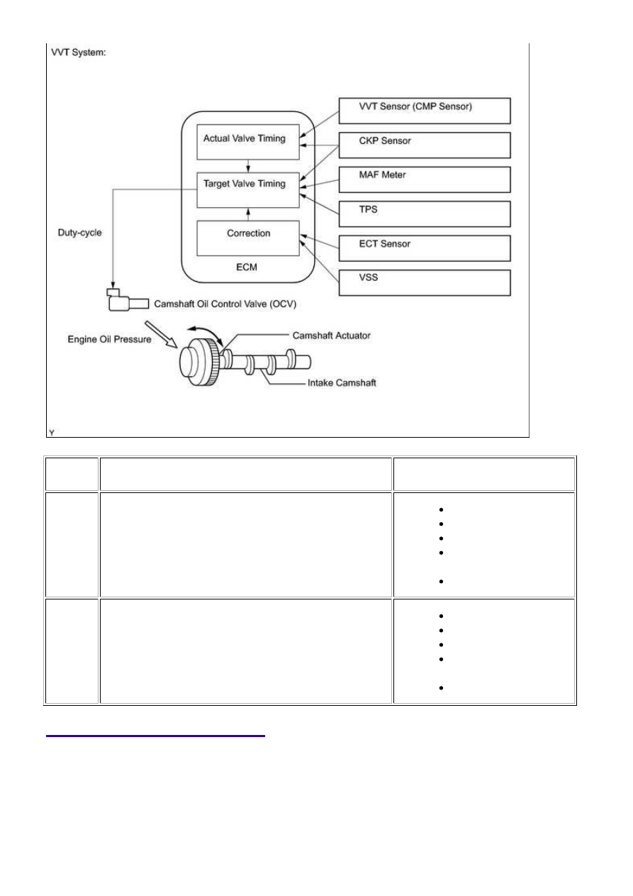
MONITOR DESCRIPTION
The ECM optimizes the intake valve timing using the VVT (Variable Valve Timing) system to control the
intake camshaft. The VVT system includes the ECM, Oil Control Valve (OCV) and VVT controller. The
ECM sends a target duty-cycle control signal to the OCV. This control signal regulates the oil pressure
supplied to the VVT controller. The VVT controller can advance or retard the intake camshaft.
If the difference between the target and actual intake valve timings is large, and changes in the actual
intake valve timing are small, the ECM interprets this as the VVT controller stuck malfunction and stores
DTC(s).
3UR-FE ENGINE CONTROL SYSTEM: SFI SYSTEM: P0011,P0012...