Toyota Tundra (2015 year). Manual - part 1873


  Index      Toyota     Toyota Tundra (2015 year) - Service and Repair Manual


Search            copyright infringement  


Content   ..  1871  1872  1873  1874   ..


Toyota Tundra (2015 year). Manual - part 1873


If a pending DTC is output, the system is malfunctioning.
If a pending DTC is not output, perform the following procedure.

Enter the following menus: Powertrain / Engine and ECT / Utility / All Readiness.

9. 

Input the DTC: P0010 or P0020.

10. 

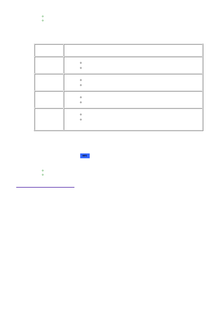
Check the DTC judgment result.

TESTER

DISPLAY

DESCRIPTION

NORMAL

DTC judgment completed

System normal

ABNORMAL

DTC judgment completed

System abnormal

INCOMPLETE

DTC judgment not completed

Perform driving pattern after confirming DTC enabling conditions

N/A

Unable to perform DTC judgment

HINT:

If the judgment result shows ABNORMAL, the system has a malfunction.

11. 

If the test result is INCOMPLETE or N/A and no pending DTC is output, perform a universal trip and

check for permanent DTCs 


.

HINT:

If a permanent DTC is output, the system is malfunctioning.
If no permanent DTC is output, the system is normal.

12. 

WIRING DIAGRAM

3UR-FE ENGINE CONTROL SYSTEM: SFI SYSTEM: P0010,P0020;...

INSPECTION PROCEDURE

HINT:

Read freeze frame data using the Techstream. Freeze frame data records the engine condition when
malfunctions are detected. When troubleshooting, freeze frame data can help determine if the vehicle
was moving or stationary, if the engine was warmed up or not, if the air-fuel ratio was lean or rich, and
other data from the time the malfunction occurred.
Bank 1 refers to the bank that includes the No. 1 cylinder*.

*: The No. 1 cylinder is the cylinder which is farthest from the transmission.

Bank 2 refers to the bank that does not include the No. 1 cylinder.

PROCEDURE

1.

CHECK DTC (DTC P0010 OR P0020)

(a) Clear DTC after recording the freeze frame data and DTC 


.

(b) Turn the ignition switch off.

(c) Allow the engine to idle and check DTC.

(d) Check that P0010 or P0020 is not present.

OK:

P0010 or P0020 is not present.

NG

GO TO STEP 2

OK

CHECK FOR INTERMITTENT PROBLEMS

3UR-FE ENGINE CONTROL SYSTEM: SFI SYSTEM: P0010,P0020;...

OK

2.

INSPECT CAMSHAFT TIMING OIL CONTROL VALVE ASSEMBLY

(a) Inspect the camshaft oil control valve assembly 


.

NG

REPLACE CAMSHAFT TIMING OIL CONTROL

VALVE ASSEMBLY

3.

CHECK HARNESS AND CONNECTOR (OCV - ECM)

(a) Disconnect the D75 or D76 OCV connector.

(b) Disconnect the D74 ECM connector.

(c) Measure the resistance according to the value(s) in the table below.

Standard resistance:

TESTER CONNECTION

CONDITION

SPECIFIED CONDITION

D75-1 - D74-58 (OC1+)

Always

Below 1 Ω

D76-1 - D74-52 (OC2+)

Always

Below 1 Ω

D75-2 - D74-57 (OC1-)

Always

Below 1 Ω

D76-2 - D74-51 (OC2-)

Always

Below 1 Ω

D75-1 or D74-58 (OC1+) - Body ground

Always

10 kΩ or higher

D76-1 or D74-52 (OC2+) - Body ground

Always

10 kΩ or higher

D75-2 or D74-57 (OC1-) - Body ground

Always

10 kΩ or higher

D76-2 or D74-51 (OC2-) - Body ground

Always

10 kΩ or higher

NG

REPAIR OR REPLACE HARNESS OR CONNECTOR

OK

REPLACE ECM

3UR-FE ENGINE CONTROL SYSTEM: SFI SYSTEM: P0010,P0020;...

Last Modified: 9-16-2014

6.6 C

Doc ID: RM000000PDU0WUX

Model Year: 2015

Model: Tundra

Prod Date Range: [08/2014 -           ]

Title: 3UR-FE ENGINE CONTROL SYSTEM: SFI SYSTEM: P0011,P0012,P0021,P0022; Camshaft Position "A" -

Timing Over-Advanced or System Performance (Bank 1); 2015 MY Tundra [08/2014 -        ]

DTC

P0011

Camshaft Position "A" - Timing Over-Advanced or System Performance

(Bank 1)

DTC

P0012

Camshaft Position "A" - Timing Over-Retarded (Bank 1)

DTC

P0021

Camshaft Position "A" - Timing Over-Advanced or System Performance

(Bank 2)

DTC

P0022

Camshaft Position "A" - Timing Over-Retarded (Bank 2)

DESCRIPTION

The VVT system includes the ECM, Oil Control Valve (OCV) and VVT controller. The ECM sends a target

duty-cycle control signal to the OCV. This control signal regulates the oil pressure supplied to the VVT

controller. Camshaft timing control is performed according to engine operating conditions such as the intake

air volume, throttle valve position and engine coolant temperature. The ECM controls the OCV, based on the

signals transmitted by several sensors. The VVT controller regulates the intake camshaft angle using oil

conditions. The ECM detects the actual intake valve timing using signals from the camshaft and crankshaft

position sensors, and performs feedback control. This is how the target intake valve timing is verified by the

ECM.

3UR-FE ENGINE CONTROL SYSTEM: SFI SYSTEM: P0011,P0012...


Content   ..  1871  1872  1873  1874   ..