Toyota Tundra (2015 year). Manual - part 1845


  Index      Toyota     Toyota Tundra (2015 year) - Service and Repair Manual


Search            copyright infringement  


Content   ..  1843  1844  1845  1846   ..


Toyota Tundra (2015 year). Manual - part 1845


(a) Install the heated oxygen sensor to the front No. 2 exhaust

pipe assembly by hand.

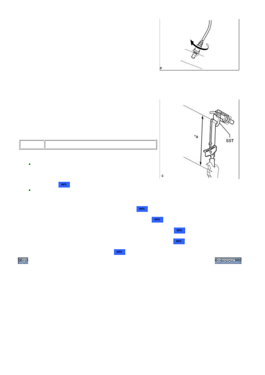
(b) Using SST, tighten the heated oxygen sensor.

SST: 09224-00010

Torque:

without SST -

44 N·m {449 kgf·cm, 32ft·lbf}

with SST -

40 N·m {408 kgf·cm, 30ft·lbf}

Text in Illustration

*a

Fulcrum length

HINT:


.

Make sure SST and the wrench are connected in a straight
line.

3. INSTALL FRONT EXHAUST PIPE ASSEMBLY 

4. INSTALL FRONT NO. 2 EXHAUST PIPE ASSEMBLY 

5. INSTALL FRONT PROPELLER SHAFT ASSEMBLY (for 4WD) 

6. INSTALL PROPELLER SHAFT HEAT INSULATOR (for 4WD) 

7. INSPECT FOR EXHAUST GAS LEAK 

3UR-FE ENGINE CONTROL SYSTEM: HEATED OXYGEN SENSOR...

Last Modified: 9-16-2014

6.6 G

Doc ID: RM00000322N00PX

Model Year: 2015

Model: Tundra

Prod Date Range: [08/2014 -           ]

Title: 3UR-FE ENGINE CONTROL SYSTEM: IGNITION RELAY NO. 2: ON-VEHICLE INSPECTION; 2015 MY

Tundra [08/2014 -        ]

ON-VEHICLE INSPECTION

1. REMOVE INTEGRATION RELAY (UNIT E)

(a) Remove the engine room relay block cover.

(b) Using a screwdriver, detach the 2 claws and remove the

integration relay from the engine room relay block.

HINT:

Tape the screwdriver tip before use.

(c) Disconnect the 3 connectors.

2. INSPECT INTEGRATION RELAY (IG2)

NOTICE:

(1) Measure the resistance according to the value(s) in the table below.

3UR-FE ENGINE CONTROL SYSTEM: IGNITION RELAY NO. 2: ...

Standard resistance:

TESTER CONNECTION

CONDITION

SPECIFIED CONDITION

IG2 MAIN fuse

Always

Below 1 Ω

If the result is not as specified, replace the IG2 MAIN fuse.

(1) Measure the resistance according to the value(s) in the

table below.

Standard resistance:

TESTER

CONNECTION

CONDITION

SPECIFIED

CONDITION

1C-1 - 1B-8

When battery voltage is not

applied to terminals 1B-6 and

1B-7

10 kΩ or higher

When battery voltage is

applied to terminals 1B-6 and

1B-7

Below 1 Ω

If the result is not as specified, replace the integration

relay.

3. INSTALL INTEGRATION RELAY (UNIT E)

(a) Connect the 3 connectors.

(b) Install the integration relay to the engine room relay block.

(c) Install the engine room relay block cover.

3UR-FE ENGINE CONTROL SYSTEM: IGNITION RELAY NO. 2: ...

Last Modified: 9-16-2014

6.6 K

Doc ID: RM0000031ZX020X

Model Year: 2015

Model: Tundra

Prod Date Range: [08/2014 -           ]

Title: 3UR-FE ENGINE CONTROL SYSTEM: KNOCK SENSOR: COMPONENTS; 2015 MY Tundra [08/2014 -        ]

COMPONENTS

ILLUSTRATION

3UR-FE ENGINE CONTROL SYSTEM: KNOCK SENSOR: COMP...


Content   ..  1843  1844  1845  1846   ..