Toyota Tundra (2015 year). Manual - part 1846


  Index      Toyota     Toyota Tundra (2015 year) - Service and Repair Manual


Search            copyright infringement  


Content   ..  1844  1845  1846  1847   ..


Toyota Tundra (2015 year). Manual - part 1846


Last Modified: 9-16-2014

6.6 A

Doc ID: RM000002PQK03UX

Model Year: 2015

Model: Tundra

Prod Date Range: [08/2014 -           ]

Title: 3UR-FE ENGINE CONTROL SYSTEM: KNOCK SENSOR: REMOVAL; 2015 MY Tundra [08/2014 -        ]

REMOVAL

1. REMOVE INTAKE MANIFOLD

2. REMOVE NO. 2 CYLINDER HEAD COVER 

3. REMOVE NO. 1 ENGINE COVER 

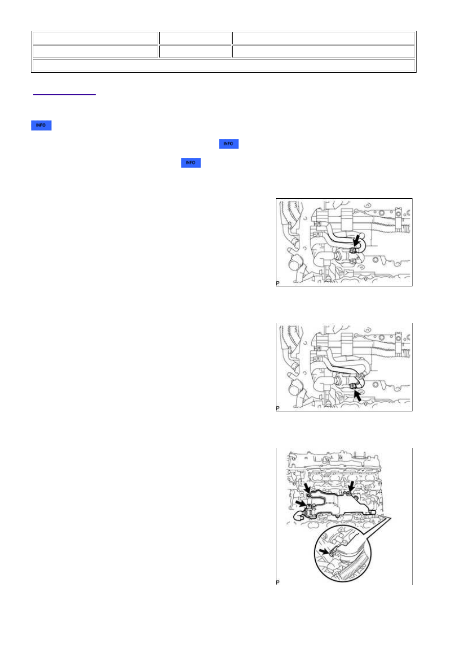
4. DISCONNECT NO. 9 WATER BY-PASS HOSE

(a) Slide the clamp and disconnect the No. 9 water by-pass hose

from the separator case.

5. DISCONNECT NO. 10 WATER BY-PASS HOSE

(a) Slide the clamp and disconnect the No. 10 water by-pass

hose from the separator case.

6. REMOVE SEPARATOR CASE

(a) Remove the 4 bolts and separator case.

7. REMOVE KNOCK SENSOR

3UR-FE ENGINE CONTROL SYSTEM: KNOCK SENSOR: REMOVA...

(a) Disconnect the 4 knock sensor connectors.

(b) Remove the 4 bolts and 4 knock sensors.

3UR-FE ENGINE CONTROL SYSTEM: KNOCK SENSOR: REMOVA...

Last Modified: 9-16-2014

6.6 G

Doc ID: RM000002PQI03BX

Model Year: 2015

Model: Tundra

Prod Date Range: [08/2014 -           ]

Title: 3UR-FE ENGINE CONTROL SYSTEM: KNOCK SENSOR: INSPECTION; 2015 MY Tundra [08/2014 -        ]

INSPECTION

1. INSPECT KNOCK SENSOR

(a) Measure the resistance according to the value(s) in the table

below.

Standard resistance:

TESTER CONNECTION

CONDITION

SPECIFIED CONDITION

1 - 2

20°C (68°F)

120 k to 280 kΩ

If the result is not as specified, replace the sensor.

3UR-FE ENGINE CONTROL SYSTEM: KNOCK SENSOR: INSPEC...

Last Modified: 9-16-2014

6.6 A

Doc ID: RM000002TKY02IX

Model Year: 2015

Model: Tundra

Prod Date Range: [08/2014 -           ]

Title: 3UR-FE ENGINE CONTROL SYSTEM: KNOCK SENSOR: INSTALLATION; 2015 MY Tundra [08/2014 -

       ]

INSTALLATION

HINT:

Perform "Inspection After Repairs" after replacing the knock sensor 


.

1. INSTALL KNOCK SENSOR

HINT:

Perform "Inspection After Repairs" after replacing the knock sensor 


.

(a) Install the 4 knock sensors with the 4 bolts so that the knock

sensors are angled as shown in the illustration.

Torque:

20 N·m {204 kgf·cm, 15ft·lbf}

Text in Illustration

*a

Bank 2 Sensor 1

*b

Bank 1 Sensor 1

*c

Bank 2 Sensor 2

*d

Bank 1 Sensor 2

*e

Front

*f

Upper

*g

Rear

NOTICE:

(b) Connect the 4 knock sensor connectors.

2. INSTALL SEPARATOR CASE

(a) Install the separator case with the 4 bolts.

Torque:

10 N·m {102 kgf·cm, 7ft·lbf}

3. CONNECT NO. 10 WATER BY-PASS HOSE

3UR-FE ENGINE CONTROL SYSTEM: KNOCK SENSOR: INSTAL...


Content   ..  1844  1845  1846  1847   ..