Content .. 1716 1717 1718 1719 ..
Toyota Tundra (2015 year). Manual - part 1718
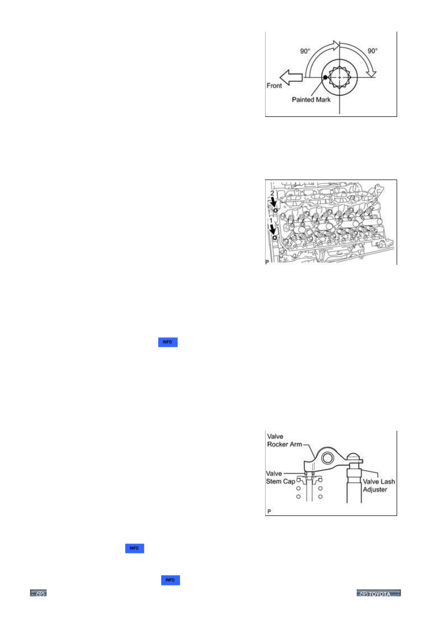
(d) Step 2:
(1) Mark each cylinder head bolt head with paint as shown in
the illustration.
(2) Tighten the cylinder head bolts another 90° in the
sequence shown in step 1.
(e) Step 3:
(1) Tighten the cylinder head bolts an additional 90° in the sequence shown in step 1.
(2) Check that the painting marks are now facing rearward.
(f) Install and uniformly tighten the 2 bolts in the sequence
shown in the illustration.
Torque:
21 N·m {214 kgf·cm, 15ft·lbf}
5. INSTALL VALVE STEM CAP
6. INSTALL VALVE LASH ADJUSTER ASSEMBLY
(a) Inspect the valve lash adjuster
.
(b) Install the 16 valve lash adjusters to the cylinder head.
NOTICE:
Install the lash adjuster at the same place it was removed from.
7. INSTALL NO. 1 VALVE ROCKER ARM SUB-ASSEMBLY
(a) Apply engine oil to the lash adjuster tips and valve stem cap ends.
(b) Install the 16 valve rocker arms as shown in the illustration.
8. INSTALL CAMSHAFTS (for Bank 2)
(a) Install the camshafts
.
9. INSTALL EXHAUST MANIFOLD SUB-ASSEMBLY RH
(a) Install the exhaust manifold RH
.
3UR-FBE ENGINE MECHANICAL: CYLINDER HEAD GASKET (fo...