Toyota Tundra (2015 year). Manual - part 1646


  Index      Toyota     Toyota Tundra (2015 year) - Service and Repair Manual


Search            copyright infringement  


Content   ..  1644  1645  1646  1647   ..


Toyota Tundra (2015 year). Manual - part 1646


A

This DTC relates to the Accelerator Pedal Position (APP) sensor.
Read freeze frame data using the Techstream. Freeze frame data records the engine condition when
malfunctions are detected. When troubleshooting, freeze frame data can help determine if the vehicle
was moving or stationary, if the engine was warmed up or not, if the air-fuel ratio was lean or rich, and
other data from the time the malfunction occurred.

PROCEDURE

1.

CHECK ANY OTHER DTCS OUTPUT (IN ADDITION TO DTC P2121)

(a) Connect the Techstream to the DLC3.

(b) Turn the ignition switch to ON.

(c) Turn the Techstream on.

(d) Enter the following menus: Powertrain / Engine and ECT / Trouble Codes.

(e) Read DTCs.

Result

RESULT

PROCEED TO

P2121 is output

A

P2121 and other DTCs are output

B

HINT:

If any DTCs other than P2121 are output, troubleshoot those DTCs first.

B

GO TO DTC CHART

2.

READ VALUE USING TECHSTREAM (ACCELERATOR POSITION SENSOR)

(a) Connect the Techstream to the DLC3.

(b) Turn the ignition switch to ON and turn the Techstream

on.

(c) Enter the following menus: Powertrain / Engine and ECT

/ Data List / ETCS / Accel Sensor Out No. 1 and Accel
Sensor Out No. 2.

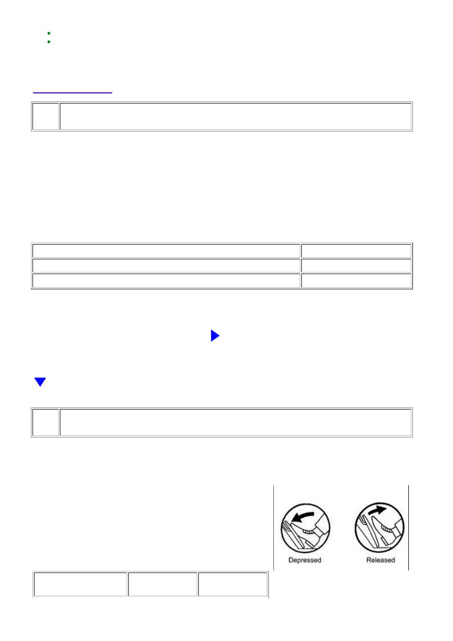
(d) Read the values displayed on the Techstream.

Standard voltage:

ACCELERATOR PEDAL

OPERATION

ACCEL SENSOR

OUT NO. 1

ACCEL SENSOR

OUT NO. 2

3UR-FBE ENGINE CONTROL SYSTEM: SFI SYSTEM: P2121; Throt...

NEXT

ACCELERATOR PEDAL

OPERATION

ACCEL SENSOR

OUT NO. 1

ACCEL SENSOR

OUT NO. 2

Released

0.5 to 1.1 V

1.2 to 2.0 V

Depressed

2.6 to 4.5 V

3.4 to 4.75 V

NG

GO TO STEP 3

OK

CHECK FOR INTERMITTENT PROBLEMS

3.

REPLACE ACCELERATOR PEDAL ASSEMBLY

(a) Replace the accelerator pedal assembly 


.

4.

CHECK WHETHER DTC OUTPUT RECURS (DTC P2121)

(a) Connect the Techstream to the DLC3.

(b) Turn the ignition switch to ON and turn the Techstream on.

(c) Clear DTCs 


.

(d) Turn the ignition switch off and wait for at least 30 seconds.

(e) Turn the ignition switch to ON and turn the Techstream on.

(f) Drive the vehicle in accordance with the driving pattern described in Confirmation Driving

Pattern.

(g) Enter the following menus: Powertrain / Engine and ECT / Trouble Codes.

(h) Read DTCs.

Result

RESULT

PROCEED TO

P2121 is output

A

No DTC is output

B

B

SYSTEM OK

A

REPLACE ECM

3UR-FBE ENGINE CONTROL SYSTEM: SFI SYSTEM: P2121; Throt...

Last Modified: 9-16-2014

6.6 C

Doc ID: RM000000WC40WEX

Model Year: 2015

Model: Tundra

Prod Date Range: [08/2014 -           ]

Title: 3UR-FBE ENGINE CONTROL SYSTEM: SFI SYSTEM: P2195-P2198; Oxygen (A/F) Sensor Signal Stuck

Lean (Bank 1 Sensor 1); 2015 MY Tundra [08/2014 -        ]

DTC

P2195

Oxygen (A/F) Sensor Signal Stuck Lean (Bank 1 Sensor 1)

DTC

P2196

Oxygen (A/F) Sensor Signal Stuck Rich (Bank 1 Sensor 1)

DTC

P2197

Oxygen (A/F) Sensor Signal Stuck Lean (Bank 2 Sensor 1)

DTC

P2198

Oxygen (A/F) Sensor Signal Stuck Rich (Bank 2 Sensor 1)

CAUTION / NOTICE / HINT

DESCRIPTION

The A/F sensor generates a voltage* that corresponds to the actual air-fuel ratio. This sensor voltage is used

to provide the ECM with feedback so that it can control the air-fuel ratio. The ECM determines the deviation

from the stoichiometric air-fuel ratio level, and regulates the fuel injection time. If the A/F sensor

malfunctions, the ECM is unable to control the air-fuel ratio accurately.

The A/F sensor is the planar type and is integrated with the heater, which heats the solid electrolyte (zirconia

element). This heater is controlled by the ECM. When the intake air volume is low (the exhaust gas

temperature is low), a current flows into the heater to heat the sensor in order to facilitate accurate air-fuel

ratio detection. In addition, the sensor and heater portions are the narrow type. The heat generated by the

heater is conducted to the solid electrolyte through the alumina, therefore the sensor activation is accelerated.

must be precisely controlled so that it is always close to the stoichiometric level.

*: Value changes inside the ECM. Since the A/F sensor is the current output element, a current is converted

into a voltage inside the ECM. Any measurements taken at the A/F sensor or ECM connectors will show a

constant voltage.

3UR-FBE ENGINE CONTROL SYSTEM: SFI SYSTEM: P2195-P219...

DTC

CODE

DTC DETECTION CONDITION

TROUBLE AREA

P2195

P2197

Conditions (a) and (b) continue for 5 seconds or more

(2 trip detection logic):

(a) Air fuel ratio sensor voltage is higher than 3.8 V.

(b) Heated oxygen sensor voltage is 0.21 V or higher.

Open or short in A/F

sensor (for Sensor 1)

circuit

A/F sensor (for Sensor 1)

A/F sensor heater (for

Sensor 1)

Integration relay

A/F sensor heater and

integration relay circuits

Air induction system

Fuel pressure

Injector

ECM

While fuel-cut operation performed (during vehicle

deceleration), A/F sensor current 2.2 mA or more for 3

seconds (2 trip detection logic)

A/F sensor

ECM

P2196

P2198

Conditions (a) and (b) continue for 5 seconds or more

(2 trip detection logic):

(a) Air fuel ratio sensor voltage is below 2.8 V.

(b) Heated oxygen sensor voltage is below 0.59 V.

Open or short in A/F

sensor (for Sensor 1)

circuit

A/F sensor (for Sensor 1)

A/F sensor heater (for

Sensor 1)

Integration relay

A/F sensor heater and

integration relay circuits

Air induction system

Fuel pressure

Injector

ECM

3UR-FBE ENGINE CONTROL SYSTEM: SFI SYSTEM: P2195-P219...


Content   ..  1644  1645  1646  1647   ..