Toyota Tundra (2015 year). Manual - part 1644


  Index      Toyota     Toyota Tundra (2015 year) - Service and Repair Manual


Search            copyright infringement  


Content   ..  1642  1643  1644  1645   ..


Toyota Tundra (2015 year). Manual - part 1644


Connect the Techstream to the DLC3.

1. 

Turn the ignition switch to ON and turn the Techstream on.

2. 

Clear DTCs (even if no DTCs are stored, perform the clear DTC operation).

3. 

Turn the ignition switch off and wait for at least 30 seconds.

4. 

Turn the ignition switch to ON and turn the Techstream on [A].

5. 

Fully depress and release the accelerator pedal [B].

6. 

Check that 5 seconds or more have elapsed since the ignition switch was turned to ON.

7. 

Enter the following menus: Powertrain / Engine and ECT / Trouble Codes [C].

8. 

Read the pending DTC.

HINT:

If a pending DTC is output, the system is malfunctioning.
If a pending DTC is not output, perform the following procedure.

9. 

Enter the following menus: Powertrain / Engine and ECT / Utility / All Readiness.

10. 

Input the DTC: P2120, P2122, P2123, P2125, P2127, P2128 or P2138.

11. 

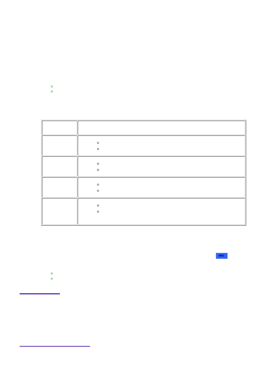
Check the DTC judgment result.

TESTER

DISPLAY

DESCRIPTION

NORMAL

DTC judgment completed

System normal

ABNORMAL

DTC judgment completed

System abnormal

INCOMPLETE

DTC judgment not completed

Perform driving pattern after confirming DTC enabling conditions

N/A

Unable to perform DTC judgment

HINT:

If the judgment result shows ABNORMAL, the system has a malfunction.

12. 

If the judgment result shows INCOMPLETE or N/A, perform steps [B] through [C] again.

13. 

If no pending DTC is output, perform a universal trip and check for permanent DTCs 


.

HINT:

If a permanent DTC is output, the system is malfunctioning.
If no permanent DTC is output, the system is normal.

14. 

FAIL-SAFE

When DTC P2120, P2121, P2122, P2123, P2125, P2127, P2128 or P2138 is stored, the ECM enters fail safe

and the engine idles.

Fail-safe mode continues until a pass condition is detected, and the ignition switch is turned off.

WIRING DIAGRAM

3UR-FBE ENGINE CONTROL SYSTEM: SFI SYSTEM: P2120,P212...

INSPECTION PROCEDURE

HINT:

These DTCs relate to the Accelerator Pedal Position (APP) sensor.
Read freeze frame data using the Techstream. Freeze frame data records the engine condition when
malfunctions are detected. When troubleshooting, freeze frame data can help determine if the vehicle
was moving or stationary, if the engine was warmed up or not, if the air-fuel ratio was lean or rich, and
other data from the time the malfunction occurred.

PROCEDURE

1.

READ VALUE USING TECHSTREAM (ACCELERATOR POSITION SENSOR)

(a) Connect the Techstream to the DLC3.

(b) Turn the ignition switch to ON and turn the Techstream

on.

(c) Enter the following menus: Powertrain / Engine and ECT

/ Data List / Accel Sensor Out No. 1 and Accel Sensor Out
No. 2.

(d) Read the value displayed on the Techstream.

Standard voltage:

ACCELERATOR

PEDAL

OPERATION

ACCEL SENSOR OUT

NO. 1

ACCEL SENSOR OUT

NO. 2

Released →
Depressed →
Released

0.5 to 4.5 V

1.2 to 4.75 V

Difference between

Accel Sensor Out No. 1

and Accel Sensor Out

No. 2 is higher than

0.02 V

Difference between

Accel Sensor Out No. 1

and Accel Sensor Out

No. 2 is higher than

0.02 V

3UR-FBE ENGINE CONTROL SYSTEM: SFI SYSTEM: P2120,P212...

A

OK

Result

RESULT

PROCEED TO

NG

A

OK

B

B

GO TO STEP 5

2.

CHECK HARNESS AND CONNECTOR (ACCELERATOR PEDAL POSITION SENSOR -
ECM)

(a) Disconnect the A14 APP sensor connector.

(b) Disconnect the A24 ECM connector.

(c) Measure the resistance according to the value(s) in the table below.

Standard resistance:

TESTER CONNECTION

CONDITION

SPECIFIED CONDITION

A14-6 (VPA) - A24-55 (VPA)

Always

Below 1 Ω

A14-5 (EPA) - A24-58 (EPA)

Always

Below 1 Ω

A14-4 (VCPA) - A24-57 (VCPA)

Always

Below 1 Ω

A14-3 (VPA2) - A24-56 (VPA2)

Always

Below 1 Ω

A14-2 (EPA2) - A24-60 (EPA2)

Always

Below 1 Ω

A14-1 (VCP2) - A24-59 (VCP2)

Always

Below 1 Ω

A14-6 (VPA) or A24-55 (VPA) - Body ground

Always

10 kΩ or higher

A14-5 (EPA) or A24-58 (EPA) - Body ground

Always

10 kΩ or higher

A14-4 (VCPA) or A24-57 (VCPA) - Body ground

Always

10 kΩ or higher

A14-3 (VPA2) or A24-56 (VPA2) - Body ground

Always

10 kΩ or higher

A14-2 (EPA2) or A24-60 (EPA2) - Body ground

Always

10 kΩ or higher

A14-1 (VCP2) or A24-59 (VCP2) - Body ground

Always

10 kΩ or higher

NG

REPAIR OR REPLACE HARNESS OR CONNECTOR

3UR-FBE ENGINE CONTROL SYSTEM: SFI SYSTEM: P2120,P212...

OK

NEXT

3.

CHECK ECM (VCPA AND VCP2 VOLTAGE)

(a) Disconnect the A14 APP sensor connector.

(b) Turn the ignition switch to ON.

(c) Measure the voltage according to the value(s) in the

table below.

Standard voltage:

TESTER CONNECTION

SWITCH

CONDITION

SPECIFIED

CONDITION

A14-4 (VCPA) - A14-5

(EPA)

Ignition switch ON 4.5 to 5.5 V

A14-1 (VCP2) - A14-2

(EPA2)

Ignition switch ON 4.5 to 5.5 V

NG

REPLACE ECM

4.

REPLACE ACCELERATOR PEDAL ASSEMBLY

(a) Replace the accelerator pedal assembly 


.

5.

CHECK WHETHER DTC OUTPUT RECURS (ACCELERATOR PEDAL POSITION
SENSOR DTCS)

(a) Connect the Techstream to the DLC3.

(b) Turn the ignition switch to ON and turn the Techstream on.

(c) Clear DTCs 


.

(d) Drive the vehicle in accordance with the driving pattern described in the Confirmation Driving

Pattern.

(e) Read DTCs.

Result

3UR-FBE ENGINE CONTROL SYSTEM: SFI SYSTEM: P2120,P212...


Content   ..  1642  1643  1644  1645   ..