Toyota Tundra (2015 year). Manual - part 1640


  Index      Toyota     Toyota Tundra (2015 year) - Service and Repair Manual


Search            copyright infringement  


Content   ..  1638  1639  1640  1641   ..


Toyota Tundra (2015 year). Manual - part 1640


The ECM monitors the battery supply voltage applied to the throttle actuator.

When the power supply voltage (+BM) drops below 4 V for 0.8 seconds or more, the ECM interprets this as an

open in the power supply circuit (+BM). The ECM illuminates the MIL and stores the DTC.

If the malfunction is not repaired successfully, the DTC is stored 5 seconds after the engine is next started.

MONITOR STRATEGY

Related DTCs

P2118: Throttle actuator power supply

Required Sensors/Components (Main)

Throttle actuator, throttle valve, ETCS fuse

Required Sensors/Components (Related)

None

Duration

0.8 seconds

MIL Operation

Immediate

TYPICAL ENABLING CONDITIONS

Monitor runs whenever following DTCs not stored

None

Battery voltage

8 V or more

Electronic throttle actuator power

ON

TYPICAL MALFUNCTION THRESHOLDS

Throttle actuator power supply voltage (+BM)

Less than 4 V

COMPONENT OPERATING RANGE

Throttle actuator power supply voltage (+BM)

11 to 14 V

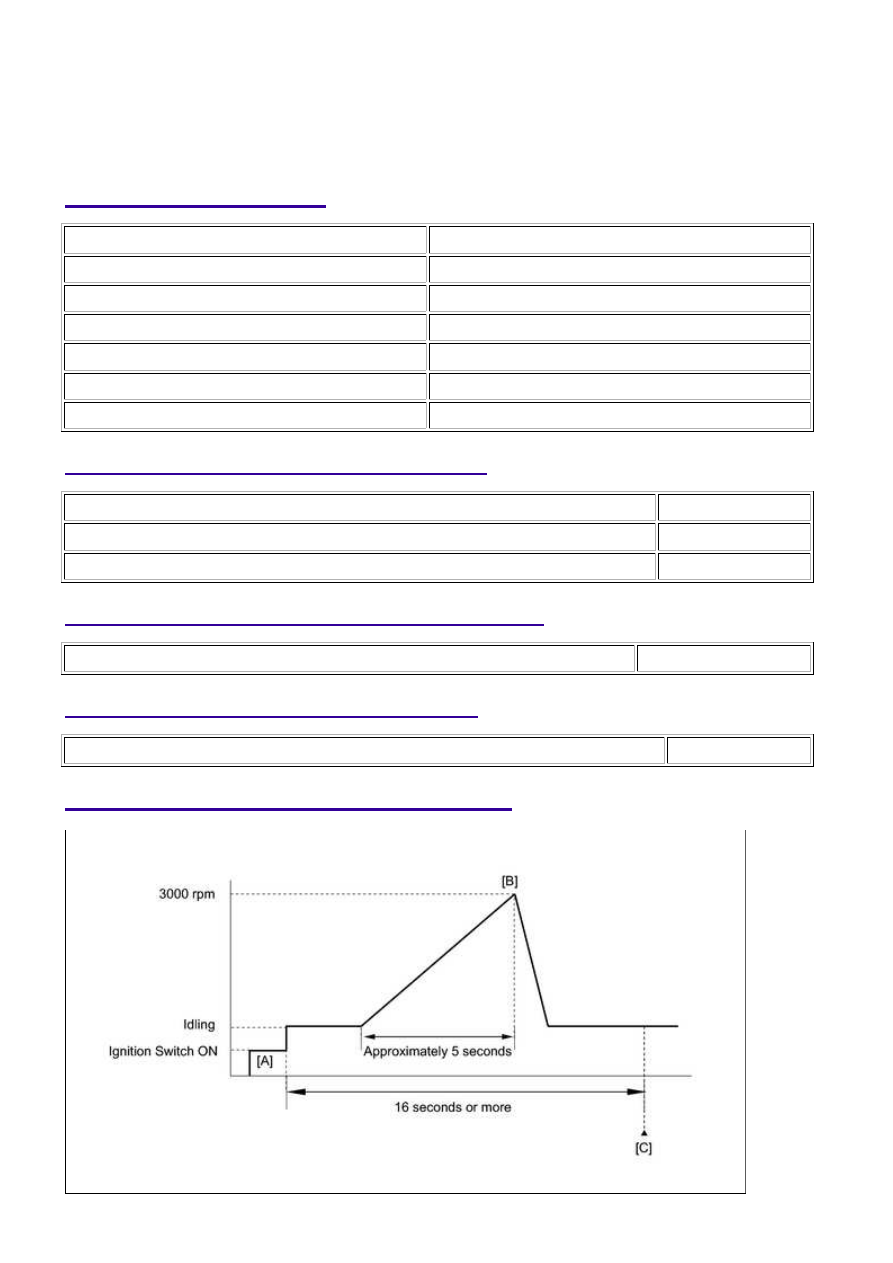
CONFIRMATION DRIVING PATTERN

3UR-FBE ENGINE CONTROL SYSTEM: SFI SYSTEM: P2118; Thrott...

Connect the Techstream to the DLC3.

1. 

Turn the ignition switch to ON and turn the Techstream on.

2. 

Clear DTCs (even if no DTCs are stored, perform the clear DTC operation).

3. 

Turn the ignition switch off and wait for at least 30 seconds.

4. 

Turn the ignition switch to ON and turn the Techstream on [A].

5. 

Start the engine.

6. 

Slowly depress the accelerator pedal, raise the engine speed to approximately 3000 rpm over

approximately 5 seconds, and then idle the engine [B].

7. 

Check that 16 seconds or more have elapsed since the engine was started.

8. 

Enter the following menus: Powertrain / Engine and ECT / Trouble Codes [C].

9. 

Read the pending DTC.

HINT:

If a pending DTC is output, the system is malfunctioning.
If a pending DTC is not output, perform the following procedure.

10. 

Enter the following menus: Powertrain / Engine and ECT / Utility / All Readiness.

11. 

Input the DTC: P2118.

12. 

Check the DTC judgment result.

TESTER

DISPLAY

DESCRIPTION

NORMAL

DTC judgment completed

System normal

ABNORMAL

DTC judgment completed

System abnormal

INCOMPLETE

DTC judgment not completed

Perform driving pattern after confirming DTC enabling conditions

N/A

Unable to perform DTC judgment

HINT:

If the judgment result shows ABNORMAL, the system has a malfunction.

13. 

If the judgment result shows INCOMPLETE or N/A, perform steps [B] through [C] again.

14. 

If no pending DTC is output, perform a universal trip and check for permanent DTCs 


.

HINT:

If a permanent DTC is output, the system is malfunctioning.
If no permanent DTC is output, the system is normal.

15. 

FAIL-SAFE

When this DTC, or other DTCs relating to ETCS (Electronic Throttle Control System) malfunctions, is stored,

the ECM enters fail-safe mode. During fail-safe mode, the ECM cuts the current to the throttle actuator, and

the throttle valve is returned to a 7° throttle angle by the return spring. The ECM then adjusts the engine

output by controlling the fuel injection (intermittent fuel-cut) and ignition timing, in accordance with the

accelerator pedal opening angle, to allow the vehicle to continue at a minimal speed. If the accelerator pedal

is depressed firmly and gently, the vehicle can be driven slowly.

Fail-safe mode continues until a pass condition is detected, and the ignition switch is then turned OFF.

3UR-FBE ENGINE CONTROL SYSTEM: SFI SYSTEM: P2118; Thrott...

WIRING DIAGRAM

INSPECTION PROCEDURE

NOTICE:

Read freeze frame data using the Techstream. Freeze frame data records the engine condition when

malfunctions are detected. When troubleshooting, freeze frame data can help determine if the vehicle
was moving or stationary, if the engine was warmed up or not, if the air-fuel ratio was lean or rich, and
other data from the time the malfunction occurred.

PROCEDURE

1.

READ VALUE USING TECHSTREAM (+BM VOLTAGE)

(a) Connect the Techstream to the DLC3.

(b) Turn the ignition switch to ON.

(c) Turn the Techstream on.

(d) Enter the following menus: Powertrain / Engine and ECT / Data List / All Data / +BM Voltage.

(e) Read the value displayed on the Techstream.

Result

3UR-FBE ENGINE CONTROL SYSTEM: SFI SYSTEM: P2118; Thrott...

A

RESULT

PROCEED TO

Less than 11 V or more than 14 V

A

11 to 14 V

B

B

CHECK FOR INTERMITTENT PROBLEMS

2.

CHECK HARNESS AND CONNECTOR (ECM - BATTERY, GROUND)

(a) Disconnect the D74 ECM connector.

(b) Measure the voltage according to the value(s) in the table below.

Standard Voltage:

TESTER CONNECTION

CONDITION

SPECIFIED CONDITION

D74-41 (+BM) - Body ground

Always

11 to 14 V

(c) Measure the resistance according to the value(s) in the table below.

Standard Resistance:

TESTER CONNECTION

CONDITION

SPECIFIED CONDITION

D74-81 (E1) - Body ground

Always

Below 1 Ω

D74-82 (ME01) - Body ground

Always

Below 1 Ω

NG

REPAIR OR REPLACE HARNESS OR CONNECTOR

OK

REPLACE ECM

3UR-FBE ENGINE CONTROL SYSTEM: SFI SYSTEM: P2118; Thrott...


Content   ..  1638  1639  1640  1641   ..