Toyota Tundra (2015 year). Manual - part 1634


  Index      Toyota     Toyota Tundra (2015 year) - Service and Repair Manual


Search            copyright infringement  


Content   ..  1632  1633  1634  1635   ..


Toyota Tundra (2015 year). Manual - part 1634


OK

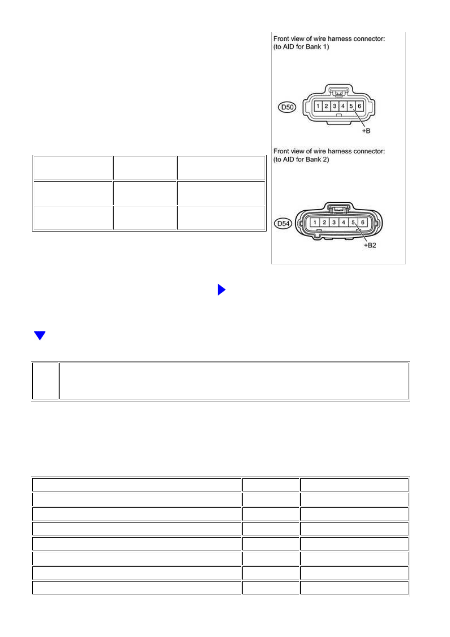
(a) Disconnect the D50 or D54 Air Injection Control Driver

(AID) connector.

(b) Turn the ignition switch to ON.

(c) Measure the voltage according to the value(s) in the

table below.

Standard voltage:

TESTER CONNECTION

SWITCH

CONDITION

SPECIFIED CONDITION

D50-5 (+B) - Body

ground

Ignition switch

ON

11 to 14 V (near battery

voltage)

D54-5 (+B2) - Body

ground

Ignition switch

ON

11 to 14 V (near battery

voltage)

NG

REPAIR OR REPLACE HARNESS OR CONNECTOR

3.

CHECK HARNESS AND CONNECTOR (AIR INJECTION CONTROL DRIVER - ECM,
BODY GROUND)

(a) Disconnect the A24 or D74 ECM connector.

(b) Disconnect the D50 or D54 AID connector.

(c) Measure the resistance according to the value(s) in the table below.

Standard resistance:

TESTER CONNECTION

CONDITION

SPECIFIED CONDITION

D74-54 (AIRP) - D50-4 (SIP)

Always

Below 1 Ω

D74-28 (AIRV) - D50-3 (SIV)

Always

Below 1 Ω

D74-53 (ARP2) - D54-4 (SIP2)

Always

Below 1 Ω

A24-43 (ARV2) - D54-3 (SIV2)

Always

Below 1 Ω

D74-30 (AIDI) - D50-2 (DI)

Always

Below 1 Ω

D74-29 (AID2) - D54-2 (DI2)

Always

Below 1 Ω

D50-1 (E) - Body ground

Always

Below 1 Ω

3UR-FBE ENGINE CONTROL SYSTEM: SFI SYSTEM: P1613,P1614...

OK

OK

TESTER CONNECTION

CONDITION

SPECIFIED CONDITION

D54-1 (E2) - Body ground

Always

Below 1 Ω

D74-54 (AIRP) or D50-4 (SIP) - Body ground

Always

10 kΩ or higher

D74-28 (AIRV) or D50-3 (SIV) - Body ground

Always

10 kΩ or higher

D74-53 (ARP2) or D54-4 (SIP2) - Body ground

Always

10 kΩ or higher

A24-43 (ARV2) or D54-3 (SIV2) - Body ground

Always

10 kΩ or higher

D74-30 (AIDI) or D50-2 (DI) - Body ground

Always

10 kΩ or higher

D74-29 (AID2) or D54-2 (DI2) - Body ground

Always

10 kΩ or higher

NG

REPAIR OR REPLACE HARNESS OR CONNECTOR

4.

INSPECT AIR INJECTION CONTROL DRIVER (DI TERMINAL VOLTAGE)

(a) Disconnect the D50 or D54 AID connector.

(b) Turn the ignition switch to ON.

(c) Measure the voltage according to the value(s) in the

table below.

Standard voltage:

TESTER

CONNECTION

SWITCH

CONDITION

SPECIFIED CONDITION

D50-2 (DI) - D50-1

(E)

Ignition switch

ON

11 to 14 V (near battery

voltage)

D54-2 (DI2) - D54-1

(E2)

Ignition switch

ON

11 to 14 V (near battery

voltage)

NG

REPLACE ECM

3UR-FBE ENGINE CONTROL SYSTEM: SFI SYSTEM: P1613,P1614...

5.

PERFORM ACTIVE TEST USING TECHSTREAM

(a) Disconnect the D50 or D54 AID connector.

(d) Turn the ignition switch to ON and turn the Techstream on.

(e) Enter the following menus: Powertrain / Engine and ECT / Utility / Secondary Air Injection

Check / Manual Mode / AIR PUMP 1: ON, ASV 1: OPEN, AIR PUMP 2: ON, ASV 2: OPEN.

HINT:

When Manual Mode is selected, the Techstream initialization (atmospheric pressure measurement) is

performed automatically. The initialization takes 10 seconds. After the initialization, AIR PUMP and ASV
operation can be selected.

(f) Start the engine.

(g) Perform the AIR system forced operation while the engine is idling.

3UR-FBE ENGINE CONTROL SYSTEM: SFI SYSTEM: P1613,P1614...

(i) Turn the ignition switch off.

NOTICE:

TESTER CONNECTION

CONDITION

SPECIFIED CONDITION

D50-3 (SIV) - D50-1 (E)

AIR PUMP: ON, ASV: OPEN

0.5 to 2 V

D54-3 (SIV2) - D54-1 (E2)

AIR PUMP: ON, ASV: OPEN

0.5 to 2 V

D50-3 (SIV) - D50-1 (E)

AIR PUMP: OFF, ASV: CLOSE

11 to 14 V

D54-3 (SIV2) - D54-1 (E2)

AIR PUMP: OFF, ASV: CLOSE

11 to 14 V

(k) Connect the Techstream to the DLC3.

(l) Turn the ignition switch to ON and turn the Techstream on.

(m) Enter the following menus: Powertrain / Engine and ECT / Utility / Secondary Air Injection

3UR-FBE ENGINE CONTROL SYSTEM: SFI SYSTEM: P1613,P1614...


Content   ..  1632  1633  1634  1635   ..