Toyota Tundra (2015 year). Manual - part 149


  Index      Toyota     Toyota Tundra (2015 year) - Service and Repair Manual


Search            copyright infringement  


Content   ..  147  148  149  150   ..


Toyota Tundra (2015 year). Manual - part 149


Last Modified: 9-16-2014

6.6 J

Doc ID: RM000004UCT00NX

Model Year: 2015

Model: Tundra

Prod Date Range: [08/2014 -           ]

Title: PARK ASSIST / MONITORING: BLIND SPOT MONITOR SYSTEM: Main Switch Circuit; 2015 MY Tundra

[08/2014 -        ]

Main Switch Circuit

DESCRIPTION

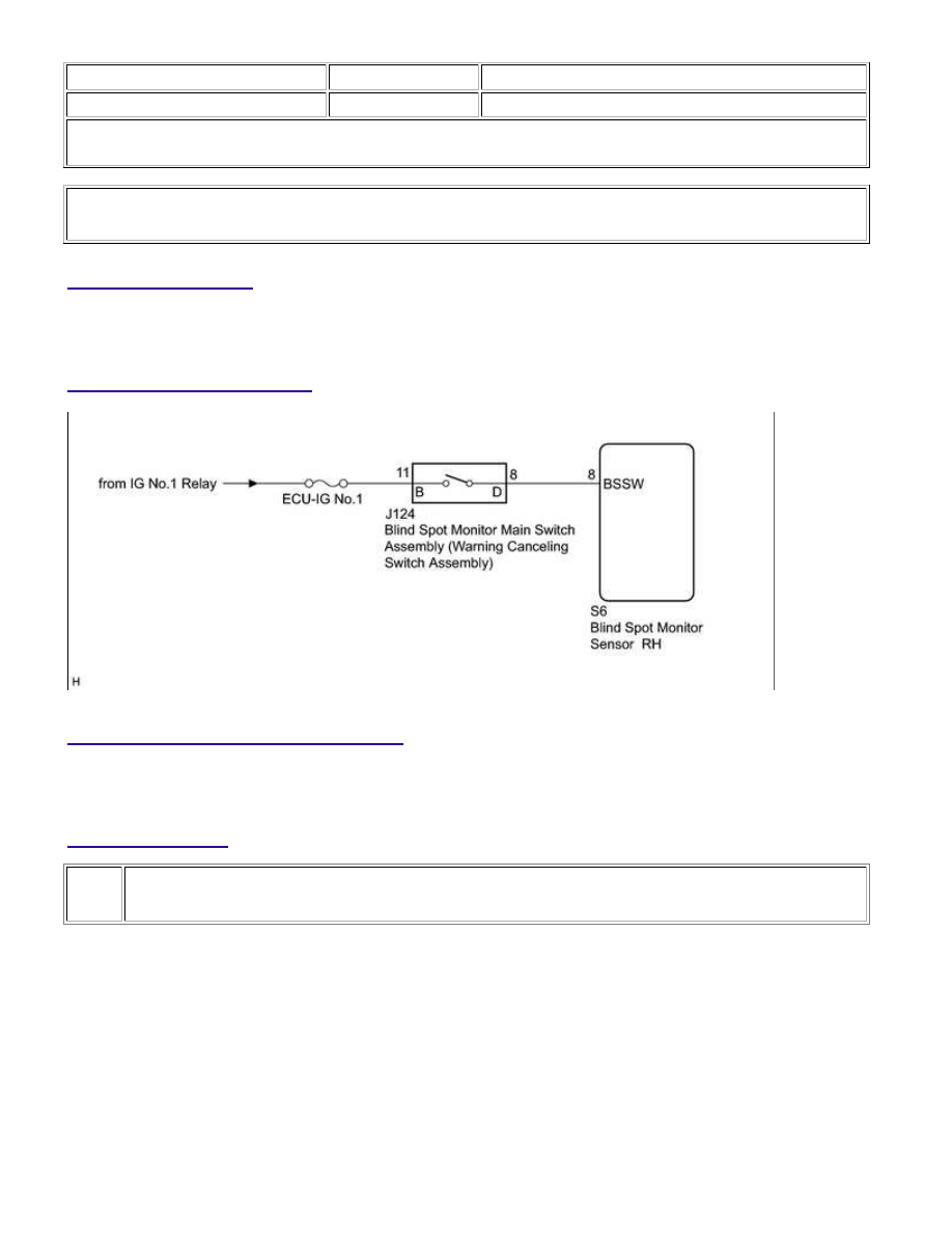
When the blind spot monitor main switch assembly (warning canceling switch assembly) is turned on, a signal is

sent to the blind spot monitor sensor RH. The blind spot monitor system operates according to this signal.

WIRING DIAGRAM

INSPECTION PROCEDURE

NOTICE:

Inspect the fuse for circuits related to this system before performing the following inspection procedure.

PROCEDURE

1.

READ VALUE USING TECHSTREAM

(a) Connect the Techstream to the DLC3.

(b) Turn the ignition switch to ON.

(c) Turn the Techstream on.

(d) Enter the following menus: Body Electrical / Blind Spot Monitor Master / Data List.

(e) According to the display on the Techstream, read the Data List.

Blind Spot Monitor Master

PARK ASSIST / MONITORING: BLIND SPOT MONITOR SYSTEM:...

OK

TESTER

DISPLAY

MEASUREMENT ITEM/RANGE

NORMAL CONDITION

DIAGNOSTIC

NOTE

Main SW

Blind spot monitor main switch assembly

(warning canceling switch assembly) /

OFF or ON

ON: Blind spot monitor main switch

assembly (warning canceling switch

assembly) on

OFF: Blind spot monitor main switch

assembly (warning canceling switch

assembly) off

-

Result

RESULT

PROCEED

TO

The display changes as shown above when the blind spot monitor main switch assembly (warning

canceling switch assembly) is operated.

A

The display does not change as shown above when the blind spot monitor main switch assembly

(warning canceling switch assembly) is operated.

B

B

GO TO STEP 2

A

PROCEED TO NEXT SUSPECTED AREA SHOWN IN

PROBLEM SYMPTOMS TABLE

2.

INSPECT BLIND SPOT MONITOR MAIN SWITCH ASSEMBLY (WARNING CANCELING
SWITCH ASSEMBLY)

(a) Remove the blind spot monitor main switch assembly (warning canceling switch assembly) 


.

(b) Inspect the blind spot monitor main switch assembly (warning canceling switch assembly) 


.

NG

REPLACE BLIND SPOT MONITOR MAIN SWITCH

ASSEMBLY (WARNING CANCELING SWITCH

ASSEMBLY)

3.

CHECK HARNESS AND CONNECTOR (BLIND SPOT MONITOR MAIN SWITCH ASSEMBLY
- BATTERY)

PARK ASSIST / MONITORING: BLIND SPOT MONITOR SYSTEM:...

OK

(a) Disconnect the blind spot monitor main switch assembly

(warning canceling switch assembly) connector.

(b) Measure the voltage according to the value(s) in the table below.

Standard Voltage:

TESTER CONNECTION

SWITCH CONDITION

SPECIFIED CONDITION

J124-11 (B) - Body ground

Ignition switch ON

11 to 14 V

J124-11 (B) - Body ground

Ignition switch off

Below 1 V

Text in Illustration

*a

NG

REPAIR OR REPLACE HARNESS OR CONNECTOR

4.

CHECK HARNESS AND CONNECTOR (BLIND SPOT MONITOR MAIN SWITCH ASSEMBLY
- BLIND SPOT MONITOR SENSOR RH)

(a) Disconnect the S6 blind spot monitor sensor RH connector.

(b) Disconnect the J124 blind spot monitor main switch assembly (warning canceling switch assembly)

connector.

(c) Measure the resistance according to the value(s) in the table below.

Standard Resistance:

TESTER CONNECTION

CONDITION

SPECIFIED CONDITION

S6-8 (BSSW) - J124-8 (D)

Always

Below 1 Ω

S6-8 (BSSW) - Body ground

Always

10 kΩ or higher

NG

REPAIR OR REPLACE HARNESS OR CONNECTOR

PARK ASSIST / MONITORING: BLIND SPOT MONITOR SYSTEM:...

OK

REPLACE BLIND SPOT MONITOR SENSOR RH

PARK ASSIST / MONITORING: BLIND SPOT MONITOR SYSTEM:...


Content   ..  147  148  149  150   ..