Toyota Tundra (2015 year). Manual - part 148


  Index      Toyota     Toyota Tundra (2015 year) - Service and Repair Manual


Search            copyright infringement  


Content   ..  146  147  148  149   ..


Toyota Tundra (2015 year). Manual - part 148


OK

INSPECTION PROCEDURE

NOTICE:

When checking for DTCs, make sure that the blind spot monitor main switch assembly (warning canceling
switch assembly) is on.
Inspect the fuses for circuits related to this system before performing the following inspection procedure.

PROCEDURE

1.

CHECK HARNESS AND CONNECTOR (BLIND SPOT MONITOR SENSOR RH - BLIND SPOT
MONITOR SENSOR LH)

(a) Disconnect the S6 blind spot monitor sensor RH connector.

(b) Disconnect the S5 blind spot monitor sensor LH connector.

(c) Measure the resistance according to the value(s) in the table below.

Standard Resistance:

TESTER CONNECTION

CONDITION

SPECIFIED CONDITION

S6-1 (CA2P) - S5-1 (CA2P)

Always

Below 1 Ω

S6-6 (CA2N) - S5-6 (CA2N)

Always

Below 1 Ω

NG

REPAIR OR REPLACE CAN LINE OR CONNECTOR

2.

CHECK HARNESS AND CONNECTOR (BLIND SPOT MONITOR SENSOR LH - BATTERY
AND BODY GROUND)

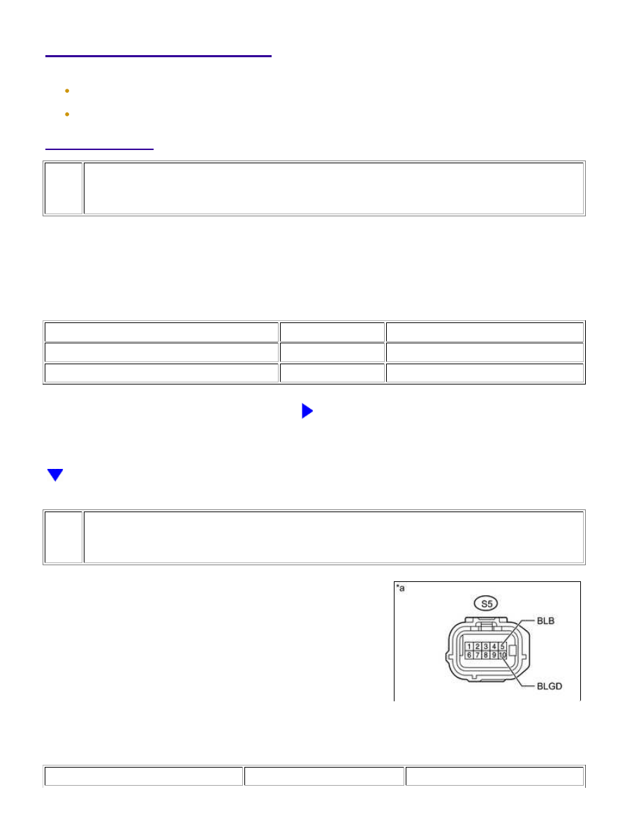
(a) Disconnect the blind spot monitor sensor LH connector.

(b) Measure the voltage according to the value(s) in the table below.

Standard Voltage:

TESTER CONNECTION

SWITCH CONDITION

SPECIFIED CONDITION

PARK ASSIST / MONITORING: BLIND SPOT MONITOR SYSTEM:...

OK

TESTER CONNECTION

SWITCH CONDITION

SPECIFIED CONDITION

S5-5 (BLB) - Body ground

Ignition switch ON

11 to 14 V

Ignition switch off

Below 1 V

(c) Measure the resistance according to the value(s) in the table below.

Standard Resistance:

TESTER CONNECTION

CONDITION

SPECIFIED CONDITION

S5-10 (BLGD) - Body ground

Always

Below 1 Ω

Text in Illustration

*a

NG

REPAIR OR REPLACE HARNESS OR CONNECTOR

3.

CHECK BLIND SPOT MONITOR SENSOR LH

(a) Replace the blind spot monitor sensor LH with a new or normally functioning one 


.

(b) Clear the DTCs 


.

(c) Recheck for DTCs and check if the same DTC is output again 


.

OK:

No DTCs are output.

NG

REPLACE BLIND SPOT MONITOR SENSOR RH

OK

END (BLIND SPOT MONITOR SENSOR LH IS

DEFECTIVE)

PARK ASSIST / MONITORING: BLIND SPOT MONITOR SYSTEM:...

OK

Last Modified: 9-16-2014

6.6 C

Doc ID: RM000004S2X01OX

Model Year: 2015

Model: Tundra

Prod Date Range: [08/2014 -           ]

Title: PARK ASSIST / MONITORING: BLIND SPOT MONITOR SYSTEM: U1331; Software Incompatibility with

Body Control Module "B"; 2015 MY Tundra [08/2014 -        ]

DTC

U1331

Software Incompatibility with Body Control Module "B"

DESCRIPTION

DTC

CODE

DTC DETECTION CONDITION

TROUBLE AREA

U1331

match.

Main body ECU (driver side

junction block assembly)

Blind spot monitor sensor

LH

Blind spot monitor sensor

RH

INSPECTION PROCEDURE

NOTICE:

When checking for DTCs, make sure that the blind spot monitor main switch assembly (warning canceling

switch assembly) is on.

PROCEDURE

1.

CONFIRM PART NUMBER (MAIN BODY ECU [DRIVER SIDE JUNCTION BLOCK
ASSEMBLY])

(a) Check the main body ECU (driver side junction block assembly) part number.

OK:

The part number is correct.

NG

REPLACE MAIN BODY ECU (DRIVER SIDE

JUNCTION BLOCK ASSEMBLY)

PARK ASSIST / MONITORING: BLIND SPOT MONITOR SYSTEM:...

2.

CHECK DTC

(a) Clear the DTCs 


.

(b) Recheck for DTCs and check if the same DTC is output again.

Result

RESULT

PROCEED TO

No DTC is output

A

DTC is output from the blind spot monitor sensor RH (master)

B

DTC is output from the blind spot monitor sensor LH (slave)

C

B

REPLACE BLIND SPOT MONITOR SENSOR RH

C

REPLACE BLIND SPOT MONITOR SENSOR LH

A

USE SIMULATION METHOD TO CHECK

PARK ASSIST / MONITORING: BLIND SPOT MONITOR SYSTEM:...


Content   ..  146  147  148  149   ..