Toyota Tundra (2015 year). Manual - part 1454


  Index      Toyota     Toyota Tundra (2015 year) - Service and Repair Manual


Search            copyright infringement  


Content   ..  1452  1453  1454  1455   ..


Toyota Tundra (2015 year). Manual - part 1454


Last Modified: 9-16-2014

6.6 G

Doc ID: RM00000324800OX

Model Year: 2015

Model: Tundra

Prod Date Range: [08/2014 -           ]

Title: 3UR-FBE ENGINE CONTROL SYSTEM: A/F SENSOR HEATER RELAY: ON-VEHICLE INSPECTION; 2015 MY

Tundra [08/2014 -        ]

ON-VEHICLE INSPECTION

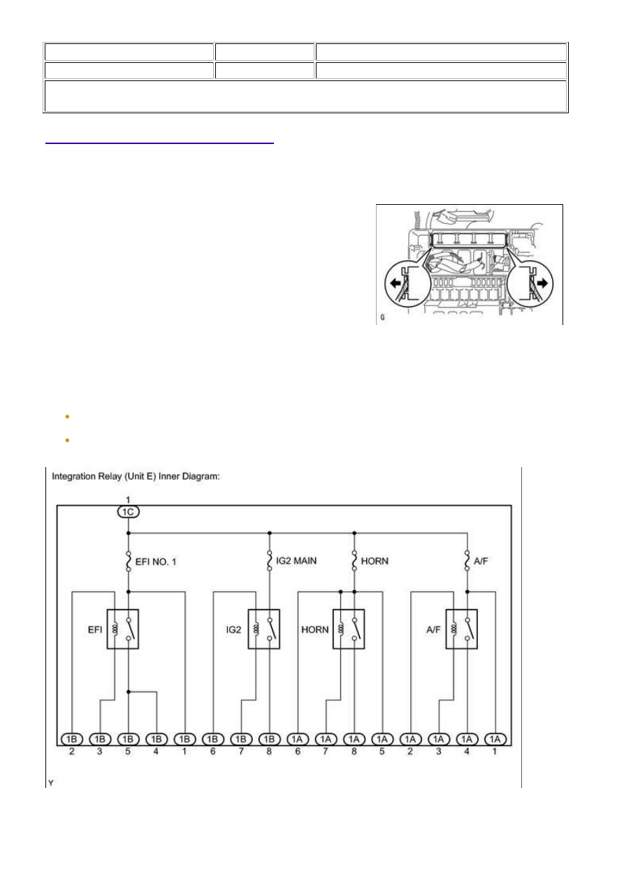
1. REMOVE INTEGRATION RELAY (UNIT E)

(a) Remove the engine room relay block cover.

(b) Using a screwdriver, detach the 2 claws and remove the

integration relay from the engine room relay block.

HINT:

Tape the screwdriver tip before use.

(c) Disconnect the 3 connectors.

2. INSPECT INTEGRATION RELAY (A/F)

NOTICE:

(1) Measure the resistance according to the value(s) in the table below.

3UR-FBE ENGINE CONTROL SYSTEM: A/F SENSOR HEATER R...

Standard Resistance:

TESTER CONNECTION

CONDITION

SPECIFIED CONDITION

A/F fuse

Always

Below 1 Ω

If the result is not as specified, replace the A/F fuse.

table below.

Standard Resistance:

TESTER

CONNECTION

CONDITION

SPECIFIED

CONDITION

1C-1 - 1A-4

When battery voltage is not

applied to terminals 1A-2 and

1A-3

10 kΩ or higher

When battery voltage is

applied to terminals 1A-2 and

1A-3

Below 1 Ω

If the result is not as specified, replace the integration

relay.

3. INSTALL INTEGRATION RELAY (UNIT E)

(a) Connect the 3 connectors.

(b) Install the integration relay to the engine room relay block.

(c) Install the engine room relay block cover.

3UR-FBE ENGINE CONTROL SYSTEM: A/F SENSOR HEATER R...

Last Modified: 9-16-2014

6.6 K

Doc ID: RM0000031WU023X

Model Year: 2015

Model: Tundra

Prod Date Range: [08/2014 -           ]

Title: 3UR-FBE ENGINE CONTROL SYSTEM: ACCELERATOR PEDAL: COMPONENTS; 2015 MY Tundra [08/2014

-        ]

COMPONENTS

ILLUSTRATION

3UR-FBE ENGINE CONTROL SYSTEM: ACCELERATOR PEDAL:...

Last Modified: 9-16-2014

6.6 G

Doc ID: RM0000031WW025X

Model Year: 2015

Model: Tundra

Prod Date Range: [08/2014 -           ]

Title: 3UR-FBE ENGINE CONTROL SYSTEM: ACCELERATOR PEDAL: ON-VEHICLE INSPECTION; 2015 MY

Tundra [08/2014 -        ]

ON-VEHICLE INSPECTION

1. INSPECT ACCELERATOR PEDAL ROD ASSEMBLY

(a) Connect the Techstream to the DLC3.

(b) Turn the ignition switch to ON.

(c) Turn the Techstream main switch on.

(d) Enter the following menus: Powertrain / Engine and ECT / Data List / ETCS / Accel Sensor Out No. 1 and

Accel Sensor Out No. 2.

(e) Read the value displayed on the tester.

Accel Sensor Out No. 1:

Standard Voltage

CONDITION

SPECIFIED CONDITION

Accelerator pedal is released

0.5 to 1.1 V

Accelerator pedal is depressed

2.6 to 4.5 V

Accel Sensor Out No. 2 :

Standard Voltage

CONDITION

SPECIFIED CONDITION

Accelerator pedal is released

1.2 to 2.0 V

Accelerator pedal is depressed

3.4 to 5.0 V

If the result is not as specified, check the accelerator pedal rod, wire harness or ECM.

3UR-FBE ENGINE CONTROL SYSTEM: ACCELERATOR PEDAL:...


Content   ..  1452  1453  1454  1455   ..