Toyota Tundra (2015 year). Manual - part 1426


  Index      Toyota     Toyota Tundra (2015 year) - Service and Repair Manual


Search            copyright infringement  


Content   ..  1424  1425  1426  1427   ..


Toyota Tundra (2015 year). Manual - part 1426


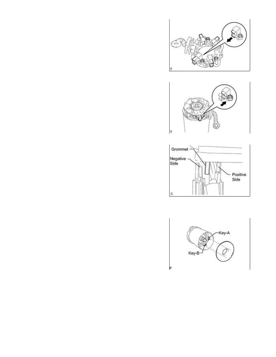
(a) Push out the 4 brushes from the brush holder so that they are

held in place by the springs as shown in the illustration.

(b) Install the brush holder to the starter armature and push in the

4 brushes.

NOTICE:

Check that the positive (+) lead wires are not grounded.

(c) Insert the grommet between the positive side and negative side.

4. INSTALL STARTER YOKE ASSEMBLY

(a) Install the starter armature plate to the starter yoke.

NOTICE:

Install the starter armature plate so that the keyway is

positioned between key A and key B.

(b) Install the starter commutator end frame with the 2 screws.

Torque:

1.5 N·m {15 kgf·cm, 13in·lbf}

1UR-FE STARTING: STARTER (for 2.0 kW Type): REASSEMBLY; 20...

(d) Using a T25 "TORX" socket wrench, install the 2 bolts.

Torque:

6.0 N·m {61 kgf·cm, 53in·lbf}

5. INSTALL MAGNET STARTER SWITCH ASSEMBLY

(a) Apply high-temperature grease to the plunger hook.

Torque:

7.5 N·m {76 kgf·cm, 66in·lbf}

(d) Connect the lead wire to the magnet starter switch with the nut.

Torque:

10 N·m {102 kgf·cm, 7ft·lbf}

1UR-FE STARTING: STARTER (for 2.0 kW Type): REASSEMBLY; 20...

Last Modified: 9-16-2014

6.6 G

Doc ID: RM000002MDL03HX

Model Year: 2015

Model: Tundra

Prod Date Range: [08/2014 -           ]

Title: 1UR-FE STARTING: STARTER (for 2.0 kW Type): INSPECTION; 2015 MY Tundra [08/2014 -        ]

INSPECTION

1. INSPECT STARTER ASSEMBLY

CAUTION:

As a large electric current passes through the cable during this inspection, a thick cable must be used.

Otherwise, the cable may become hot and cause injury.

NOTICE:

These tests must be performed within 3 to 5 seconds to avoid burning out the coil.

(a) Mount the starter in a vise between aluminum plates.

(b) Perform a pull-in test.

(1) Remove the nut and disconnect the field coil wire from terminal C.

(2) Connect the battery to the magnet starter switch as shown in

the illustration. Then check that the clutch pinion gear moves

outward.

If the clutch pinion gear does not move outward, replace the

magnet starter switch assembly.

(c) Perform a holding test.

(1) Disconnect the negative (-) lead from terminal C with the

condition specified in the pull-in test above being

maintained. Check that the pinion gear remains out.

If the clutch pinion gear moves inward, replace the magnet

starter switch assembly.

(d) Inspect clutch pinion gear return.

1UR-FE STARTING: STARTER (for 2.0 kW Type): INSPECTION; 20...

(1) Disconnect the negative (-) lead from the starter body.

Check that the clutch pinion gear moves inward.

If the clutch pinion gear does not move inward, replace the

magnet starter switch assembly.

(e) Perform an operation test without load.

(1) Connect the field coil wire to terminal C with the nut.

Torque:

10 N·m {102 kgf·cm, 7ft·lbf}

(2) Connect the battery and an ammeter to the starter as shown in the illustration.

(3) Check that the starter rotates smoothly and steadily while the pinion gear is moving outward. Then

measure the current.

Standard current:

150 A or less at 11.5 V

If the result is not as specified, replace the starter assembly.

2. INSPECT STARTER ARMATURE ASSEMBLY

If necessary, replace the starter armature assembly.

(b) Inspect the commutator for an open circuit.

1UR-FE STARTING: STARTER (for 2.0 kW Type): INSPECTION; 20...


Content   ..  1424  1425  1426  1427   ..