Content .. 1425 1426 1427 1428 ..
Toyota Tundra (2015 year). Manual - part 1427
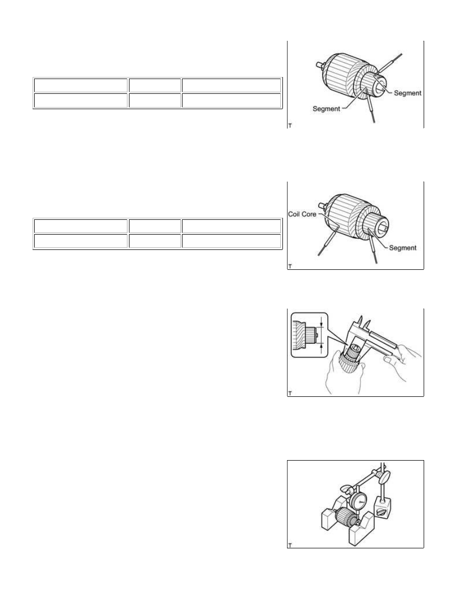
(1) Measure the resistance according to the value(s) in the table
below.
Standard Resistance:
TESTER CONNECTION
CONDITION
SPECIFIED CONDITION
Segment - Segment
Always
Below 1 Ω
If the result is not as specified, replace the starter armature
assembly.
(c) Inspect the commutator for a short circuit.
(1) Measure the resistance according to the value(s) in the table
below.
Standard Resistance:
TESTER CONNECTION
CONDITION
SPECIFIED CONDITION
Segment - Coil core
Always
10 kΩ or higher
If the result is not as specified, replace the starter armature
assembly.
(d) Using a vernier caliper, measure the commutator diameter.
Standard diameter:
29.0 mm (1.14 in.)
Minimum diameter:
28.0 mm (1.10 in.)
HINT:
Be sure to measure the commutator diameter at the ridges.
If the diameter is less than the minimum, replace the starter
armature assembly.
(e) Check the commutator runout.
(1) Place the armature shaft on V-blocks.
(2) Using a dial indicator, measure the circle runout.
Maximum commutator runout:
0.05 mm (0.00197 in.)
If the commutator runout is more than the maximum,
replace the starter armature assembly.
1UR-FE STARTING: STARTER (for 2.0 kW Type): INSPECTION; 20...