Content .. 1276 1277 1278 1279 ..
Toyota Tundra (2015 year). Manual - part 1278
data from the time the malfunction occurred.
Bank 1 refers to the bank that includes the No. 1 cylinder*.
*: The No. 1 cylinder is the cylinder which is farthest from the transmission.
Bank 2 refers to the bank that does not include the No. 1 cylinder.
Sensor 1 refers to the sensor closest to the engine assembly.
Sensor 2 refers to the sensor farthest away from the engine assembly.
PROCEDURE
1.
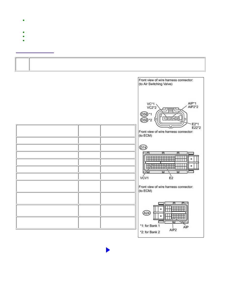
CHECK HARNESS AND CONNECTOR (AIR SWITCHING VALVE - ECM)
(a) Disconnect the air switching valve connector.
(b) Disconnect the ECM connectors.
(c) Measure the resistance according to the value(s) in the table
below.
Standard Resistance:
TESTER CONNECTION
CONDITION
SPECIFIED
CONDITION
D58-3 (AIP) - A24-54 (AIP)
Always
Below 1 Ω
D58-2 (VC) - D74-67 (VCV1)
Always
Below 1 Ω
D58-4 (E2) - D74-98 (E2)
Always
Below 1 Ω
D59-3 (AIP2) - A24-53 (AIP2)
Always
Below 1 Ω
D59-2 (VC2) - D74-67 (VCV1)
Always
Below 1 Ω
D59-4 (E22) - D74-98 (E2)
Always
Below 1 Ω
D58-3 (AIP) or A24-54 (AIP) -
Body ground
Always
10 kΩ or higher
D58-2 (VC) or D74-67 (VCV1) -
Body ground
Always
10 kΩ or higher
D59-3 (AIP2) or A24-53 (AIP2) -
Body ground
Always
10 kΩ or higher
D59-2 (VC2) or D74-67 (VCV1) -
Body ground
Always
10 kΩ or higher
NG
REPAIR OR REPLACE HARNESS OR CONNECTOR
1UR-FE ENGINE CONTROL SYSTEM: SFI SYSTEM: P2431-P2433,...