Toyota Tundra (2015 year). Manual - part 114


  Index      Toyota     Toyota Tundra (2015 year) - Service and Repair Manual


Search            copyright infringement  


Content   ..  112  113  114  115   ..


Toyota Tundra (2015 year). Manual - part 114


INSPECTION PROCEDURE

PROCEDURE

1.

CHECK HARNESS AND CONNECTOR (NAVIGATION RECEIVER ASSEMBLY - STEREO
COMPONENT AMPLIFIER ASSEMBLY)

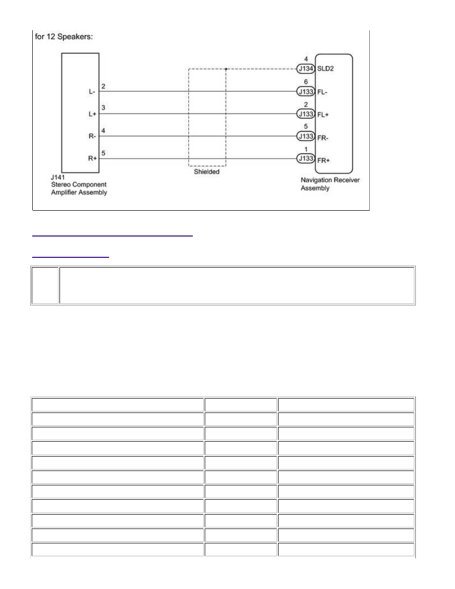
(a) for 7 or 9 Speakers:

(1) Disconnect the J134 and J133 navigation receiver assembly connectors.

(2) Disconnect the J145 stereo component amplifier assembly connector.

(3) Measure the resistance according to the value(s) in the table below.

Standard Resistance:

TESTER CONNECTION

CONDITION

SPECIFIED CONDITION

J133-2 (FL+) - J145-1 (FL+)

Always

Below 1 Ω

J133-6 (FL-) - J145-6 (FL-)

Always

Below 1 Ω

J133-1 (FR+) - J145-2 (FR+)

Always

Below 1 Ω

J133-5 (FR-) - J145-7 (FR-)

Always

Below 1 Ω

J134-2 (RL+) - J145-3 (RL+)

Always

Below 1 Ω

J134-6 (RL-) - J145-8 (RL-)

Always

Below 1 Ω

J134-1 (RR+) - J145-9 (RR+)

Always

Below 1 Ω

J134-3 (RR-) - J145-10 (RR-)

Always

Below 1 Ω

J133-2 (FL+) - Body ground

Always

10 kΩ or higher

J133-6 (FL-) - Body ground

Always

10 kΩ or higher

NAVIGATION: NAVIGATION SYSTEM: Sound Signal Circuit betwee...

TESTER CONNECTION

CONDITION

SPECIFIED CONDITION

J133-1 (FR+) - Body ground

Always

10 kΩ or higher

J133-5 (FR-) - Body ground

Always

10 kΩ or higher

J134-2 (RL+) - Body ground

Always

10 kΩ or higher

J134-6 (RL-) - Body ground

Always

10 kΩ or higher

J134-1 (RR+) - Body ground

Always

10 kΩ or higher

J134-3 (RR-) - Body ground

Always

10 kΩ or higher

(b) for 12 Speakers:

(1) Disconnect the J134 and J133 navigation receiver assembly connectors.

(2) Disconnect the J141 stereo component amplifier assembly connector.

(3) Measure the resistance according to the value(s) in the table below.

Standard Resistance:

TESTER CONNECTION

CONDITION

SPECIFIED CONDITION

J133-6 (FL-) - J141-2 (L-)

Always

Below 1 Ω

J133-2 (FL+) - J141-3 (L+)

Always

Below 1 Ω

J133-5 (FR-) - J141-4 (R-)

Always

Below 1 Ω

J133-1 (FR+) - J141-5 (R+)

Always

Below 1 Ω

J133-6 (FL-) - Body ground

Always

10 kΩ or higher

J133-2 (FL+) - Body ground

Always

10 kΩ or higher

J133-5 (FR-) - Body ground

Always

10 kΩ or higher

J133-1 (FR+) - Body ground

Always

10 kΩ or higher

J134-4 (SLD2) - Body ground

Always

10 kΩ or higher

NG

REPAIR OR REPLACE HARNESS OR CONNECTOR

OK

PROCEED TO NEXT SUSPECTED AREA SHOWN IN

PROBLEM SYMPTOMS TABLE

NAVIGATION: NAVIGATION SYSTEM: Sound Signal Circuit betwee...

Last Modified: 9-16-2014

6.6 J

Doc ID: RM0000020QE0LPX

Model Year: 2015

Model: Tundra

Prod Date Range: [08/2014 -           ]

Title: NAVIGATION: NAVIGATION SYSTEM: Sound Signal Circuit between Navigation Receiver Assembly and

Stereo Jack Adapter; 2015 MY Tundra [08/2014 -        ]

Sound Signal Circuit between Navigation Receiver Assembly and Stereo Jack Adapter

DESCRIPTION

The No. 1 stereo jack adapter assembly sends the sound signal from an external device to the navigation receiver

assembly via this circuit.

The sound signal that has been sent is amplified by the navigation receiver assembly, and then is sent to the

speakers.

If there is an open or short in the circuit, sound cannot be heard from the speakers even if there is no

malfunction in the navigation receiver assembly or speakers.

WIRING DIAGRAM

INSPECTION PROCEDURE

PROCEDURE

1.

CHECK HARNESS AND CONNECTOR (NAVIGATION RECEIVER ASSEMBLY - NO. 1

NAVIGATION: NAVIGATION SYSTEM: Sound Signal Circuit betwee...

STEREO JACK ADAPTER ASSEMBLY)

(a) Disconnect the J135 navigation receiver assembly connector.

(b) Disconnect the J100 No. 1 stereo jack adapter assembly connector.

(c) Measure the resistance according to the value(s) in the table below.

Standard Resistance:

TESTER CONNECTION

CONDITION

SPECIFIED CONDITION

J135-25 (ADPG) - J100-9 (AUXO)

Always

Below 1 Ω

J135-26 (VAR+) - J100-6 (ARO)

Always

Below 1 Ω

J135-28 (VAL+) - J100-7 (ALO)

Always

Below 1 Ω

J135-27 (VA-) - J100-8 (ASGN)

Always

Below 1 Ω

J135-11 (AGND) - J100-10 (AGND)

Always

Below 1 Ω

J135-25 (ADPG) - Body ground

Always

10 kΩ or higher

J135-26 (VAR+) - Body ground

Always

10 kΩ or higher

J135-28 (VAL+) - Body ground

Always

10 kΩ or higher

J135-27 (VA-) - Body ground

Always

10 kΩ or higher

J135-11 (AGND) - Body ground

Always

10 kΩ or higher

NG

REPAIR OR REPLACE HARNESS OR CONNECTOR

OK

PROCEED TO NEXT SUSPECTED AREA SHOWN IN

PROBLEM SYMPTOMS TABLE

NAVIGATION: NAVIGATION SYSTEM: Sound Signal Circuit betwee...


Content   ..  112  113  114  115   ..