Toyota Tundra (2015 year). Manual - part 112
A
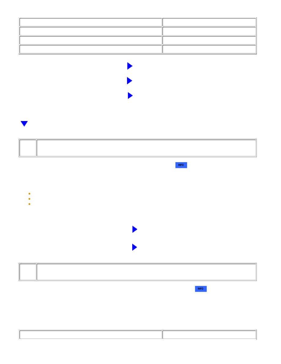
RESULT
PROCEED TO
OK (for Double Cab)
B
NG (for Double Cab)
C
NG (for CrewMax)
D
B
GO TO STEP 11
C
REPLACE REAR NO. 1 SPEAKER ASSEMBLY
D
REPLACE REAR NO. 1 SPEAKER ASSEMBLY
10.
CHECK REAR NO. 2 SPEAKER ASSEMBLY
(a) Replace the rear No. 2 speaker assembly with a known good one
.
(b) Check that the malfunction disappears.
NOTICE:
Connect all the connectors to the rear No. 2 speaker assemblies that were disconnected.
Connect all the connectors to the rear No. 2 speaker assemblies that were disconnected.
Perform the above inspection on both LH and RH sides.
OK:
Malfunction disappears.
NG
GO TO STEP 11
OK
END (REAR NO. 2 SPEAKER ASSEMBLY IS
DEFECTIVE)
11.
CHECK STEREO COMPONENT AMPLIFIER ASSEMBLY
(a) Replace the stereo component amplifier assembly with a known good one
.
(b) Check that the malfunction disappears.
OK:
Malfunction disappears.
Result
RESULT
PROCEED TO
NAVIGATION: NAVIGATION SYSTEM: Speaker Circuit; 2015 MY T...