Toyota Tundra (2015 year). Manual - part 111


  Index      Toyota     Toyota Tundra (2015 year) - Service and Repair Manual


Search            copyright infringement  


Content   ..  109  110  111  112   ..


Toyota Tundra (2015 year). Manual - part 111


B

REPLACE NAVIGATION RECEIVER ASSEMBLY

C

REPLACE NAVIGATION RECEIVER ASSEMBLY

A

END (FRONT NO. 2 SPEAKER ASSEMBLY IS

DEFECTIVE)

5.

CHECK HARNESS AND CONNECTOR (SPEAKER CIRCUIT)

*1: for RH Side

*2: for LH Side

*3: for 9 Speakers

(a) Disconnect the J133 and J134 navigation receiver assembly connector.

(b) Disconnect the M8*1 and/or N10*2 front No. 1 speaker assembly connector.

(c) Disconnect the J147*1 and/or J149*2 front No. 2 speaker assembly connector.

(d) Disconnect the J150 front No. 4 speaker assembly connector.

(e) Disconnect the O1*1 and/or O7*2 rear No. 1 speaker assembly connector.

(f) Disconnect the O2*1 and/or O8*2 rear No. 2 speaker assembly connector.*3

(g) Disconnect the J144 and J145 stereo component amplifier assembly connectors.

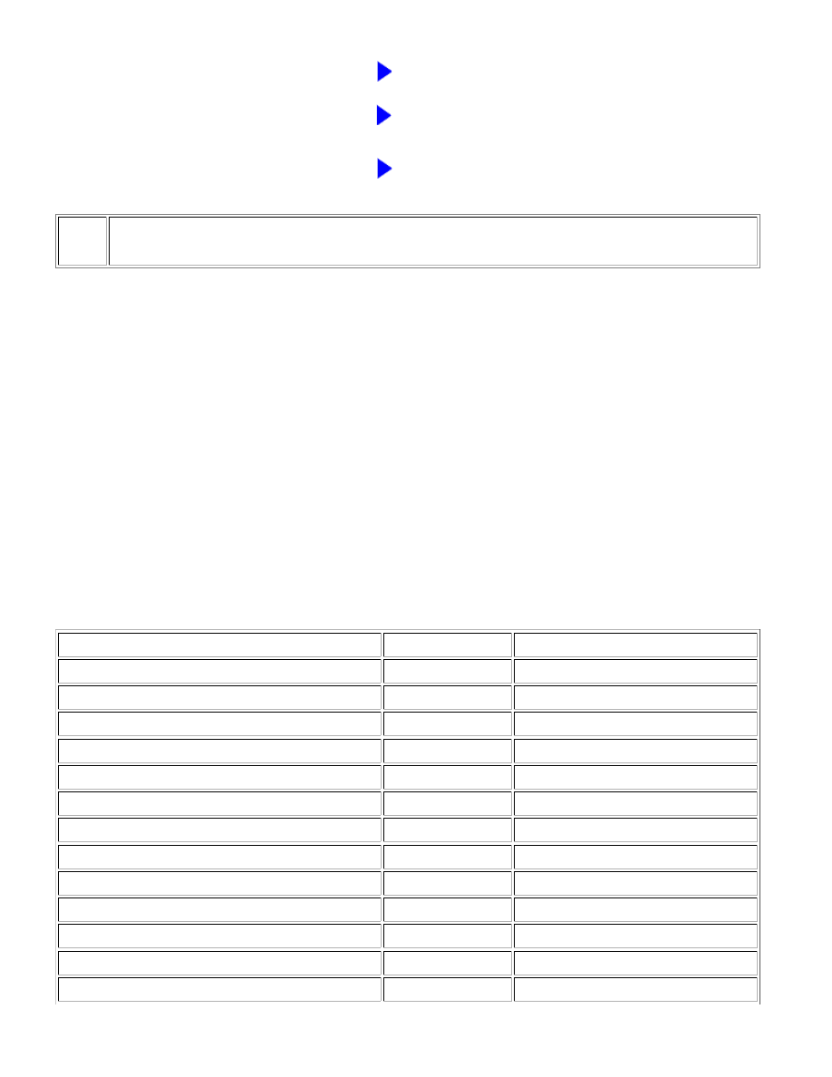
(h) Measure the resistance according to the value(s) in the table below.

Standard Resistance:

TESTER CONNECTION

CONDITION

SPECIFIED CONDITION

M8-1 - J144-1 (R+)

Always

Below 1 Ω

M8-2 - J144-5 (R-)

Always

Below 1 Ω

N10-1 - J144-2 (L+)

Always

Below 1 Ω

N10-2 - J144-6 (L-)

Always

Below 1 Ω

O1-1 - J145-4 (WFR+)

Always

Below 1 Ω

O1-2 - J145-11 (WFR-)

Always

Below 1 Ω

O7-1 - J145-5 (WFL+)

Always

Below 1 Ω

O7-2 - J145-12 (WFL-)

Always

Below 1 Ω

O2-3 - J145-9 (RR+)*3

Always

Below 1 Ω

O2-2 - J145-10 (RR-)*3

Always

Below 1 Ω

J145-9 (RR+) - J134-1 (RR+)

Always

Below 1 Ω

J145-10 (RR-) - J134-3 (RR-)

Always

Below 1 Ω

O8-3 - J145-3 (RL+)*3

Always

Below 1 Ω

NAVIGATION: NAVIGATION SYSTEM: Speaker Circuit; 2015 MY T...

TESTER CONNECTION

CONDITION

SPECIFIED CONDITION

O8-2 - J145-8 (RL-)*3

Always

Below 1 Ω

J145-3 (RL+) - J134-2 (RL+)

Always

Below 1 Ω

J145-8 (RL-) - J134-6 (RL-)

Always

Below 1 Ω

J145-2 (FR+) - J133-1 (FR+)

Always

Below 1 Ω

J145-7 (FR-) - J133-5 (FR-)

Always

Below 1 Ω

J145-1 (FL+) - J133-2 (FL+)

Always

Below 1 Ω

J145-6 (FL-) - J133-6 (FL-)

Always

Below 1 Ω

J145-2 (FR+) - J147-3 (TWR+)

Always

Below 1 Ω

J145-7 (FR-) - J147-2 (TWR-)

Always

Below 1 Ω

J145-1 (FL+) - J149-3 (TWL+)

Always

Below 1 Ω

J145-6 (FL-) - J149-2 (TWL-)

Always

Below 1 Ω

J147-1 (+) - J150-1 (+)

Always

Below 1 Ω

J147-4 (-) - J150-4 (RI1-)

Always

Below 1 Ω

J150-2 (-) - J149-4 (-)

Always

Below 1 Ω

J150-3 (RI1+) - J149-1 (+)

Always

Below 1 Ω

J144-1 (R+) - Body ground

Always

10 kΩ or higher

J144-5 (R-) - Body ground

Always

10 kΩ or higher

J144-2 (L+) - Body ground

Always

10 kΩ or higher

J144-6 (L-) - Body ground

Always

10 kΩ or higher

J145-4 (WFR+) - Body ground

Always

10 kΩ or higher

J145-11 (WFR-) - Body ground

Always

10 kΩ or higher

J145-5 (WFL+) - Body ground

Always

10 kΩ or higher

J145-12 (WFL-) - Body ground

Always

10 kΩ or higher

J145-9 (RR+) - Body ground

Always

10 kΩ or higher

J145-10 (RR-) - Body ground

Always

10 kΩ or higher

J145-3 (RL+) - Body ground

Always

10 kΩ or higher

J145-8 (RL-) - Body ground

Always

10 kΩ or higher

J145-2 (FR+) - Body ground

Always

10 kΩ or higher

J145-7 (FR-) - Body ground

Always

10 kΩ or higher

J145-1 (FL+) - Body ground

Always

10 kΩ or higher

J145-6 (FL-) - Body ground

Always

10 kΩ or higher

J147-1 (+) - Body ground

Always

10 kΩ or higher

J147-4 (-) - Body ground

Always

10 kΩ or higher

J147-3 (TWR+) - Body ground

Always

10 kΩ or higher

J147-2 (TWR-) - Body ground

Always

10 kΩ or higher

NAVIGATION: NAVIGATION SYSTEM: Speaker Circuit; 2015 MY T...

OK

A

TESTER CONNECTION

CONDITION

SPECIFIED CONDITION

J150-2 (-) - Body ground

Always

10 kΩ or higher

J150-3 (RI1+) - Body ground

Always

10 kΩ or higher

J149-3 (TWL+) - Body ground

Always

10 kΩ or higher

J149-2 (TWL-) - Body ground

Always

10 kΩ or higher

NG

REPAIR OR REPLACE HARNESS OR CONNECTOR

6.

INSPECT FRONT NO. 1 SPEAKER ASSEMBLY

(a) Remove the front No. 1 speaker assembly.

for Double Cab: 

for CrewMax: 

(b) Inspect the front No. 1 speaker assembly.

for Double Cab: 

for CrewMax: 

Result

RESULT

PROCEED TO

OK

A

NG (for Double Cab)

B

NG (for CrewMax)

C

B

REPLACE FRONT NO. 1 SPEAKER ASSEMBLY

C

REPLACE FRONT NO. 1 SPEAKER ASSEMBLY

7.

CHECK FRONT NO. 2 SPEAKER ASSEMBLY

(a) Replace the front No. 2 speaker assembly with a known good one.

NAVIGATION: NAVIGATION SYSTEM: Speaker Circuit; 2015 MY T...

for Double Cab: 

for CrewMax: 

(b) Check that the malfunction disappears.

NOTICE:

Connect all the connectors to the front No. 2 speaker assemblies that were disconnected.
Perform the above inspection on both LH and RH sides.

OK:

Malfunction disappears.

NG

GO TO STEP 8

OK

END (FRONT NO. 2 SPEAKER ASSEMBLY IS

DEFECTIVE)

8.

CHECK FRONT NO. 4 SPEAKER ASSEMBLY

(a) Replace the front No. 4 speaker assembly with a known good one.

for Double Cab: 

for CrewMax: 

(b) Check that the malfunction disappears.

OK:

Malfunction disappears.

NG

GO TO STEP 9

OK

END (FRONT NO. 4 SPEAKER ASSEMBLY IS

DEFECTIVE)

9.

CHECK REAR NO. 1 SPEAKER ASSEMBLY

(a) Remove the rear No. 1 speaker assembly with a known good one.

for Double Cab: 

for CrewMax: 

(b) Inspect the rear No. 1 speaker assembly with a known good one.

for Double Cab: 

for CrewMax: 

Result

RESULT

PROCEED TO

OK (for CrewMax)

A

NAVIGATION: NAVIGATION SYSTEM: Speaker Circuit; 2015 MY T...


Content   ..  109  110  111  112   ..