Content .. 1116 1117 1118 1119 ..
Toyota Tundra (2015 year). Manual - part 1118
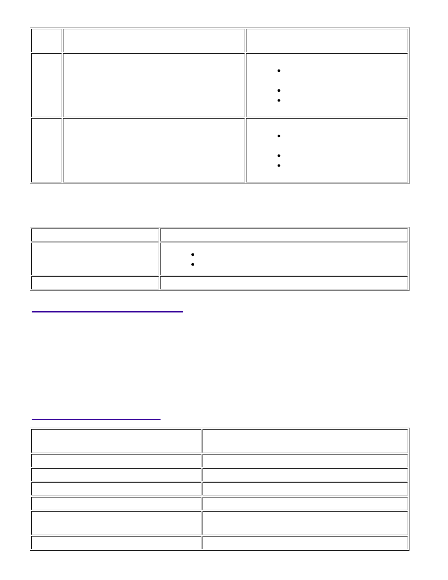
DTC
NO.
DTC DETECTION CONDITION
TROUBLE AREA
P0102
Mass air flow meter voltage is below 0.2 V for 3
seconds
(1 trip detection logic: Engine speed is less than
4000 rpm)
(2 trip detection logic: Engine speed is 4000 rpm or
more).
Open or short in mass air flow meter
circuit
Mass air flow meter
ECM
P0103
Mass air flow meter voltage is higher than 4.9 V for 3
seconds
(1 trip detection logic: Engine speed is less than
4000 rpm)
(2 trip detection logic: Engine speed is 4000 rpm or
more).
Open or short in mass air flow meter
circuit
Mass air flow meter
ECM
HINT:
MASS AIR FLOW RATE (GM/SEC.)
MALFUNCTION
Approximately 0.0
Open in Mass Air Flow (MAF) meter power source circuit
Open or short in VG circuit
160.0 or more
Open in E2G circuit
MONITOR DESCRIPTION
If there is a defect in the MAF meter or an open or short circuit, the voltage level deviates from the normal
operating range. The ECM interprets this deviation as a malfunction in the MAF meter and stores a DTC.
Example:
When the sensor output voltage remains at less than 0.2 V, or more than 4.9 V for more than 3 seconds, the ECM
stores a DTC.
If the malfunction is not repaired successfully, a DTC is stored 3 seconds after the engine is next started.
MONITOR STRATEGY
Related DTCs
P0102: MAF meter range check (Low voltage)
P0103: MAF meter range check (High voltage)
Required Sensors/Components (Main)
MAF meter
Required Sensors/Components (Related)
Crankshaft position sensor
Duration
3 seconds
MIL Operation
Immediate: Engine speed less than 4000 rpm
2 driving cycles: Engine speed 4000 rpm or more
1UR-FE ENGINE CONTROL SYSTEM: SFI SYSTEM: P0102,P0103;...