Content .. 1101 1102 1103 1104 ..
Toyota Tundra (2015 year). Manual - part 1103
If the test result is INCOMPLETE or N/A and no pending DTC is output, perform a universal trip and
check for permanent DTCs
.
HINT:
If a permanent DTC is output, the system is malfunctioning.
If no permanent DTC is output, the system is normal.
12.
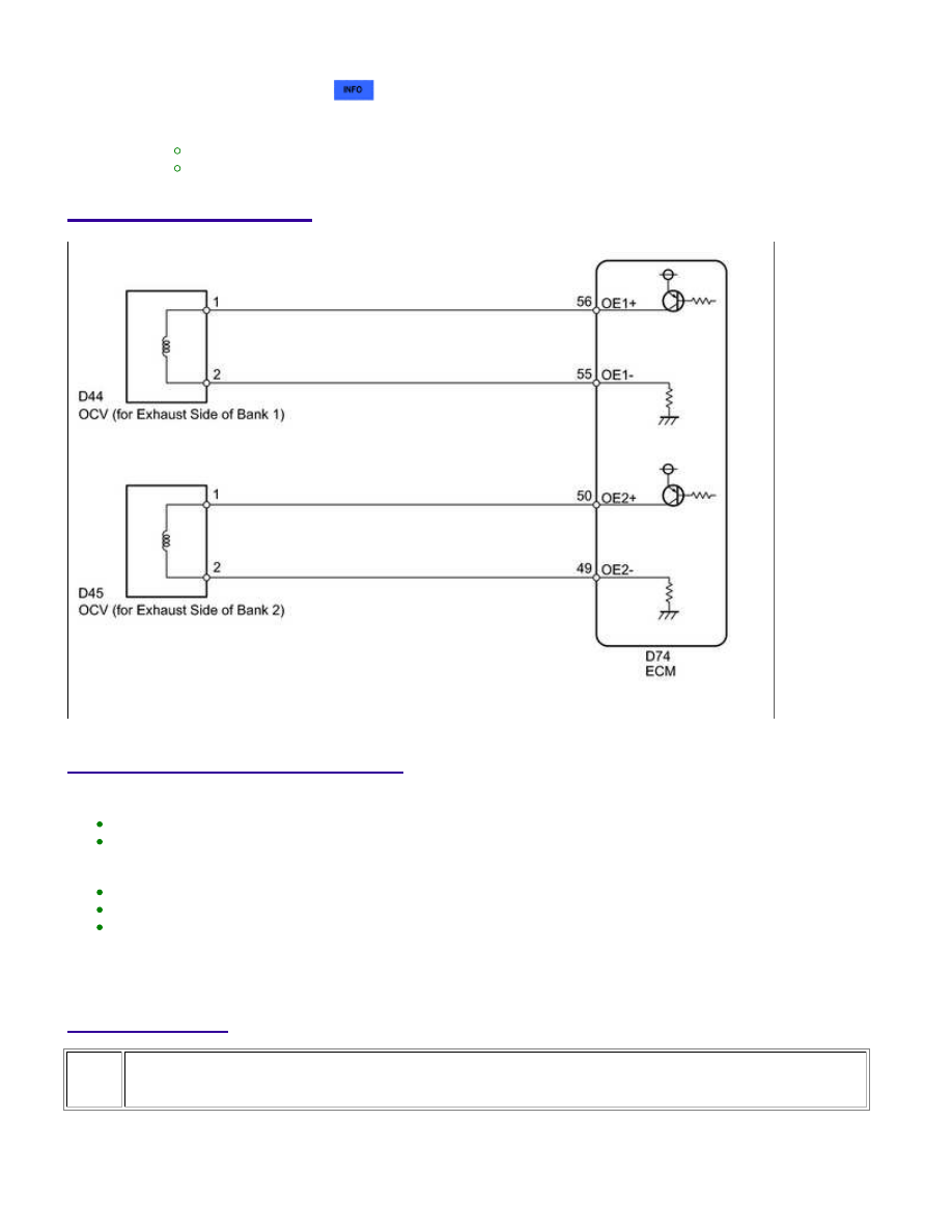
WIRING DIAGRAM
INSPECTION PROCEDURE
HINT:
If DTC P0013 is displayed, check the bank 1 VVT system for exhaust camshaft circuit.
Bank 1 refers to the bank that includes the No. 1 cylinder*.
*: The No. 1 cylinder is the cylinder which is farthest from the transmission.
If DTC P0023 is displayed, check the bank 2 VVT system for exhaust camshaft circuit.
Bank 2 refers to the bank that does not include the No. 1 cylinder.
Read freeze frame data using the Techstream. Freeze frame data records the engine condition when
malfunctions are detected. When troubleshooting, freeze frame data can help determine if the vehicle was
moving or stationary, if the engine was warmed up or not, if the air-fuel ratio was lean or rich, and other
data from the time the malfunction occurred.
PROCEDURE
1.
CHECK FOR DTC (DTC P0013 OR P0023)
(a) Connect the Techstream to the DLC3.
1UR-FE ENGINE CONTROL SYSTEM: SFI SYSTEM: P0013,P0023;...