Content .. 1060 1061 1062 1063 ..
Toyota Tundra (2015 year). Manual - part 1062
Last Modified: 9-16-2014
6.6 G
Doc ID: RM0000031YM025X
Model Year: 2015
Model: Tundra
Prod Date Range: [08/2014 - ]
Title: 1UR-FE ENGINE CONTROL SYSTEM: HEATED OXYGEN SENSOR: ON-VEHICLE INSPECTION; 2015 MY
Tundra [08/2014 - ]
ON-VEHICLE INSPECTION
1. CHECK HEATED OXYGEN SENSOR
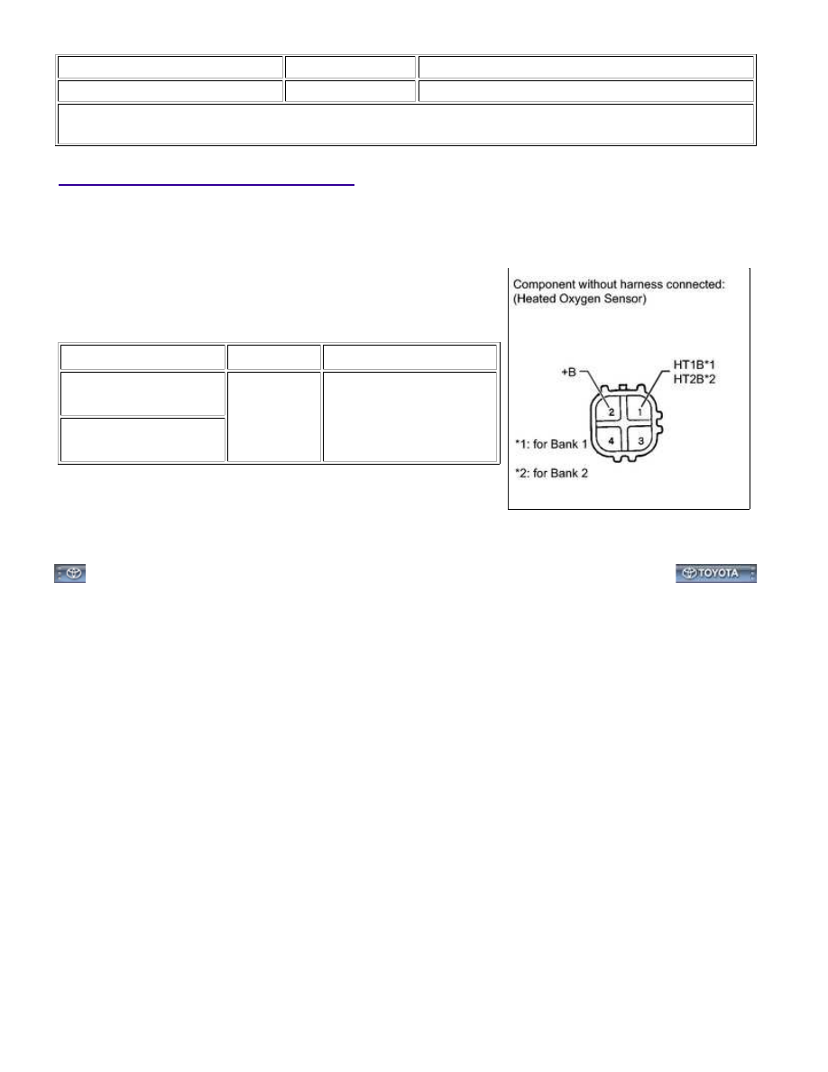
(a) Disconnect the heated oxygen sensor connector.
(b) Measure the heater resistance according to the value(s) in the
table below.
Standard Resistance:
TESTER CONNECTION
CONDITION
SPECIFIED CONDITION
1 (HT1B) - 2 (+B)
(for Bank 1)
20°C (68°F)
11 to 16 Ω
1 (HT2B) - 2 (+B)
(for Bank 2)
If the result is not as specified, replace the heated oxygen
sensor.
(c) Connect the heated oxygen sensor connector.
1UR-FE ENGINE CONTROL SYSTEM: HEATED OXYGEN SENSO...