Toyota Tundra (2015 year). Manual - part 1061


  Index      Toyota     Toyota Tundra (2015 year) - Service and Repair Manual


Search            copyright infringement  


Content   ..  1059  1060  1061  1062   ..


Toyota Tundra (2015 year). Manual - part 1061


Last Modified: 9-16-2014

6.6 G

Doc ID: RM000002PQE03GX

Model Year: 2015

Model: Tundra

Prod Date Range: [08/2014 -           ]

Title: 1UR-FE ENGINE CONTROL SYSTEM: ENGINE COOLANT TEMPERATURE SENSOR: INSPECTION; 2015 MY

Tundra [08/2014 -        ]

INSPECTION

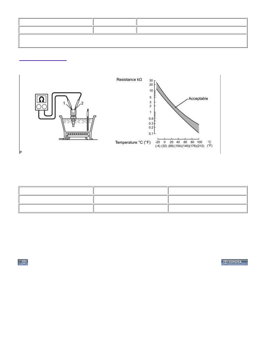
1. INSPECT ENGINE COOLANT TEMPERATURE SENSOR

(a) Partially immerse the sensor in water and warm up the water.

(b) Measure the resistance according to the value(s) in the table below.

Standard Resistance:

TESTER CONNECTION

CONDITION

SPECIFIED CONDITION

1 - 2

Approx. 20°C (68°F)

2.32 k to 2.59 kΩ

1 - 2

Approx. 80°C (176°F)

0.310 k to 0.326 kΩ

If the result is not as specified, replace the engine coolant temperature sensor.

NOTICE:

When checking the sensor in water, keep the terminals dry. After the check, wipe the sensor dry.

HINT:

If the result is as specified, do not replace the engine coolant temperature sensor.

1UR-FE ENGINE CONTROL SYSTEM: ENGINE COOLANT TEM...

Last Modified: 9-16-2014

6.6 A

Doc ID: RM000002PQD03SX

Model Year: 2015

Model: Tundra

Prod Date Range: [08/2014 -           ]

Title: 1UR-FE ENGINE CONTROL SYSTEM: ENGINE COOLANT TEMPERATURE SENSOR: INSTALLATION; 2015 MY

Tundra [08/2014 -        ]

INSTALLATION

HINT:

Perform "Inspection After Repairs" after replacing the engine coolant temperature sensor 


.

1. INSTALL ENGINE COOLANT TEMPERATURE SENSOR

HINT:

Perform "Inspection After Repairs" after replacing the engine coolant temperature sensor 


.

(a) Install a new gasket to the sensor.

(b) Using a 19 mm ball joint lock nut wrench, install the sensor.

Torque:

20 N·m {200 kgf·cm, 14ft·lbf}

NOTICE:

Use the formula to calculate special torque values for situations

where ball joint lock nut wrench is combined with a torque
wrench 


.

(c) Connect the sensor connector.

2. ADD ENGINE COOLANT 

3. INSPECT FOR COOLANT LEAK 

4. INSTALL V-BANK COVER SUB-ASSEMBLY 

5. INSTALL NO. 1 ENGINE UNDER COVER 

1UR-FE ENGINE CONTROL SYSTEM: ENGINE COOLANT TEM...

Last Modified: 9-16-2014

6.6 G

Doc ID: RM000002PQX02AX

Model Year: 2015

Model: Tundra

Prod Date Range: [08/2014 -           ]

Title: 1UR-FE ENGINE CONTROL SYSTEM: FUEL PUMP RELAY: ON-VEHICLE INSPECTION; 2015 MY Tundra

[08/2014 -        ]

ON-VEHICLE INSPECTION

1. REMOVE FUEL PUMP RELAY (F/PMP)

(a) Remove the fuel pump relay from the engine room relay block.

2. INSPECT FUEL PUMP RELAY

(a) Measure the resistance according to the value(s) in the table

below.

Standard Resistance:

TESTER

CONNECTION

CONDITION

SPECIFIED

CONDITION

3 - 5

When no battery voltage is

applied to terminals 1 and 2

10 kΩ or higher

When battery voltage is applied

to terminals 1 and 2

Below 1 Ω

If the result is not as specified, replace the fuel pump relay.

3. INSTALL FUEL PUMP RELAY

(a) Install the fuel pump relay to the engine room relay block.

1UR-FE ENGINE CONTROL SYSTEM: FUEL PUMP RELAY: ON-...

Last Modified: 9-16-2014

6.6 K

Doc ID: RM0000031YK025X

Model Year: 2015

Model: Tundra

Prod Date Range: [08/2014 -           ]

Title: 1UR-FE ENGINE CONTROL SYSTEM: HEATED OXYGEN SENSOR: COMPONENTS; 2015 MY Tundra

[08/2014 -        ]

COMPONENTS

ILLUSTRATION

1UR-FE ENGINE CONTROL SYSTEM: HEATED OXYGEN SENSO...


Content   ..  1059  1060  1061  1062   ..