Toyota Tundra (2015 year). Manual - part 1036


  Index      Toyota     Toyota Tundra (2015 year) - Service and Repair Manual


Search            copyright infringement  


Content   ..  1034  1035  1036  1037   ..


Toyota Tundra (2015 year). Manual - part 1036


Last Modified: 9-16-2014

6.6 A

Doc ID: RM0000030WH02JX

Model Year: 2015

Model: Tundra

Prod Date Range: [08/2014 -           ]

Title: 1UR-FE EMISSION CONTROL: AIR SWITCHING VALVE (for Bank 1): REMOVAL; 2015 MY Tundra [08/2014

-        ]

REMOVAL

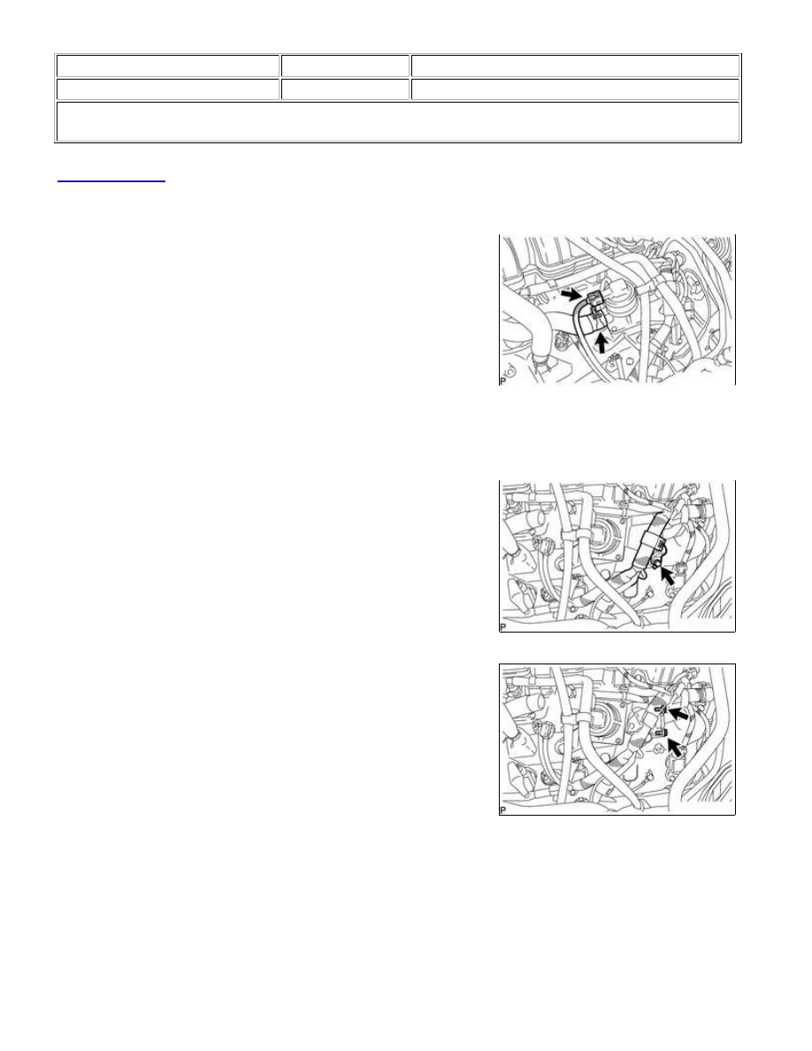
1. DISCONNECT NO. 2 AIR HOSE

(a) Disconnect the air switching valve assembly connector.

(b) Slide the clamp and disconnect the No. 2 air hose.

2. REMOVE AIR SWITCHING VALVE ASSEMBLY

(a) Remove the bolt and disconnect the wire harness clamp bracket

from the cylinder head cover.

(b) Remove the 2 bolts.

1UR-FE EMISSION CONTROL: AIR SWITCHING VALVE (for Bank 1...

(c) Remove the 3 bolts, air switching valve assembly and gasket.

NOTICE:

Last Modified: 9-16-2014

6.6 G

Doc ID: RM0000030WF02FX

Model Year: 2015

Model: Tundra

Prod Date Range: [08/2014 -           ]

Title: 1UR-FE EMISSION CONTROL: AIR SWITCHING VALVE (for Bank 1): INSPECTION; 2015 MY Tundra

[08/2014 -        ]

INSPECTION

1. INSPECT AIR SWITCHING VALVE ASSEMBLY

(a) Measure the resistance according to the value(s) in the table

below.

Standard Resistance:

TESTER CONNECTION

CONDITION

SPECIFIED CONDITION

1 - 5

20°C (68°F)

4.5 to 5.5 Ω

1 - Body ground

Always

1 MΩ or higher

5 - Body ground

Text in Illustration

*a

Component without harness connected

(Air Switching Valve Assembly)

NOTICE:

When measuring the resistance, do not touch terminals 2, 3 or 4.

HINT:

When measuring the resistance, make sure that the surface

assembly.

1UR-FE EMISSION CONTROL: AIR SWITCHING VALVE (for Bank 1...

Text in Illustration

*a

Port A

*b

Port B

Air

NOTICE:

Make sure the applied pressure is 30 kPa (0.3 kgf/cm 

2

 , 4.4 psi) or less.

If the result is not as specified, replace the air switching valve assembly.

(2) Apply battery voltage across terminals 1 and 5.

Text in Illustration

*a

Component without harness connected

(Air Switching Valve Assembly)

*b

Port A

*c

Port B

Air

NOTICE:

When applying voltage, do not touch terminals 2, 3 or 4.

(3) Check that air flows from port A to port B.

If the result is not as specified, replace the air switching valve assembly.

1UR-FE EMISSION CONTROL: AIR SWITCHING VALVE (for Bank 1...


Content   ..  1034  1035  1036  1037   ..