Content .. 1033 1034 1035 1036 ..
Toyota Tundra (2015 year). Manual - part 1035
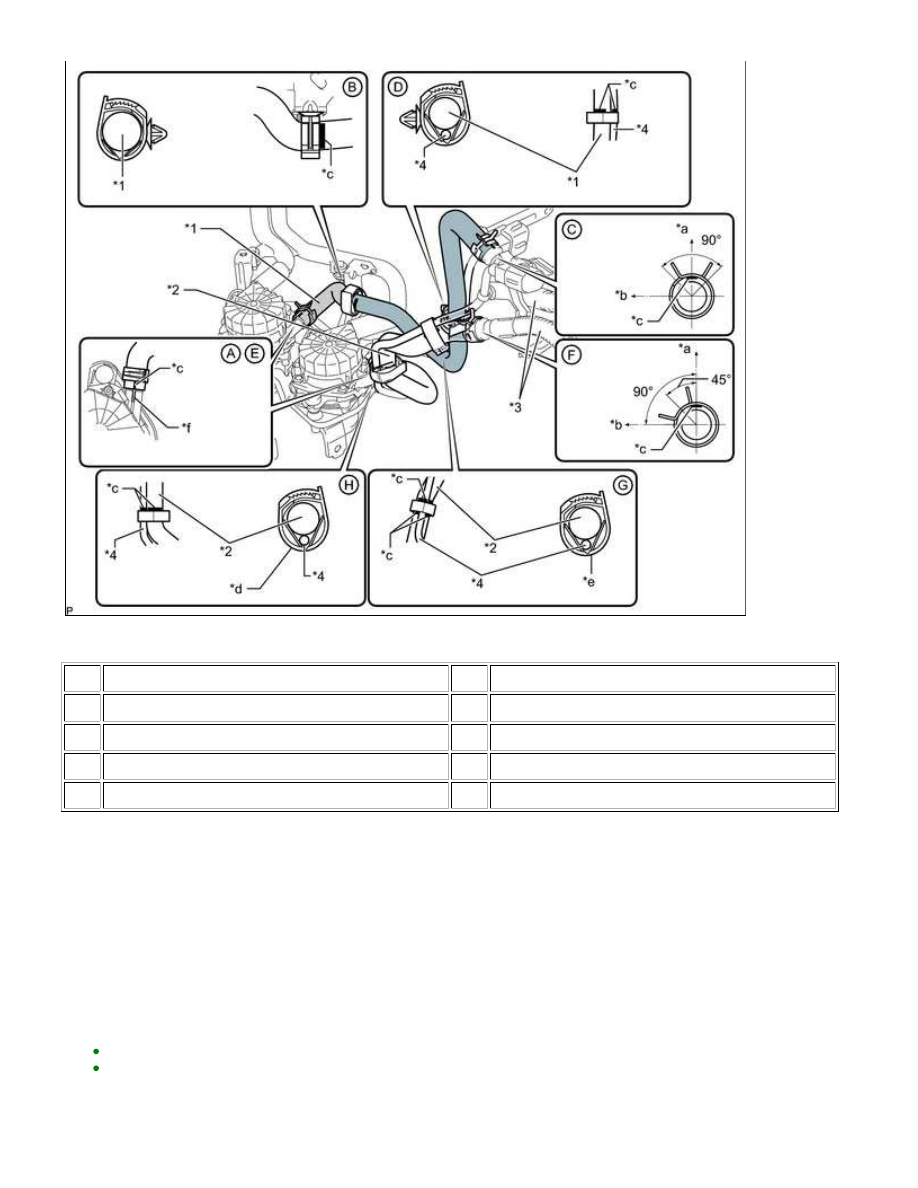
Text in Illustration
*1
No. 3 Air Injection System Hose
*2
No. 2 Air Injection System Hose
*3
Air Tube
*4
Wire Harness
*a
Upper
*b
Front
*c
Paint Mark
*d
Black Colored Clamp
*e
White Colored Clamp
*f
Rib
(a) Connect the No. 3 air injection system hose, and slide the clamp to secure the hose so that its paint mark
aligns with the air pump's rib as shown in the illustration labeled A.
(b) Attach the clamp to the No. 3 air injection system hose shown in the illustration labeled B.
HINT:
in the illustration labeled C.
HINT:
D.
1UR-FE EMISSION CONTROL: AIR PUMP: INSTALLATION; 2015...