Toyota Tundra (2015 year). Manual - part 1033


  Index      Toyota     Toyota Tundra (2015 year) - Service and Repair Manual


Search            copyright infringement  


Content   ..  1031  1032  1033  1034   ..


Toyota Tundra (2015 year). Manual - part 1033


Last Modified: 9-16-2014

6.6 G

Doc ID: RM0000040K202MX

Model Year: 2015

Model: Tundra

Prod Date Range: [08/2014 -           ]

Title: 1UR-FE EMISSION CONTROL: AIR PUMP: ON-VEHICLE INSPECTION; 2015 MY Tundra [08/2014 -        ]

ON-VEHICLE INSPECTION

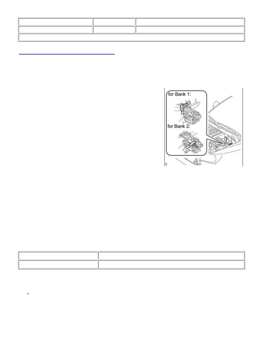
1. INSPECT AIR PUMP ASSEMBLY

(a) Start the engine and warm it up.

(b) Turn the ignition switch off.

(d) Connect the Techstream to the DLC3.

(e) Turn the ignition switch to ON and turn the Techstream on.

(f) Enter the following menus: Powertrain / Engine and ECT / Utility / Secondary Air Injection Check / Manual

Mode / AIR PUMP 1: ON, ASV1: OPEN, AIR PUMP 2: ON, ASV2: OPEN.

HINT:

When Manual Mode is selected, the Techstream initialization (atmospheric pressure measurement) is

performed automatically. The initialization takes 10 seconds. After the initialization, AIR PUMP and ASV
operation can be selected.

(g) Measure the current while the air pump assembly is turning.

Standard Current:

CONDITION

SPECIFIED CONDITION

20°C (68°F)

10 to 40 A

(h) Turn the ignition switch to off.

NOTICE:

prohibition (WAIT or ERROR).

1UR-FE EMISSION CONTROL: AIR PUMP: ON-VEHICLE INSPEC...

If an ERROR is displayed on the Techstream during the test, stop the engine for 10 minutes, and

then try again.

Last Modified: 9-16-2014

6.6 A

Doc ID: RM0000030YE01ZX

Model Year: 2015

Model: Tundra

Prod Date Range: [08/2014 -           ]

Title: 1UR-FE EMISSION CONTROL: AIR PUMP: REMOVAL; 2015 MY Tundra [08/2014 -        ]

REMOVAL

1. DISCONNECT FRONT FENDER LINER RH

HINT:

It is not necessary to fully remove the front fender liner RH.

Partially remove it so that the air pump assembly with bracket can be removed in a later step.

2. DISCONNECT FRONT FENDER APRON SEAL RH

(a) Using a clip remover, remove the 2 clips and fold back the front

fender apron seal RH.

3. REMOVE NO. 2 AIR INJECTION SYSTEM HOSE

(a) Engine Room Side:

Text in Illustration

*a

Engine Room Side

*b

Front Fender RH Inside

(1) Detach the 2 clamps.

(2) Slide the clamp indicated by the arrow in the illustration and

disconnect the No. 2 air injection system hose from the air

tube.

(b) Front Fender RH Inside:

(1) Slide the clamp and disconnect the No. 2 air injection system hose from the air pump assembly.

4. REMOVE NO. 3 AIR INJECTION SYSTEM HOSE

1UR-FE EMISSION CONTROL: AIR PUMP: REMOVAL; 2015 MY ...

(a) Engine Room Side:

Text in Illustration

*a

Engine Room Side

*b

Front Fender RH Inside

(1) Detach the clamp.

(2) Slide the clamp indicated by the arrow in the illustration and

disconnect the No. 3 air injection system hose from the air

tube.

(b) Front Fender RH Inside:

(1) Detach the clamp.

(2) Slide the clamp indicated by the arrow in the illustration and disconnect the No. 3 air injection system

hose from the air pump assembly.

5. REMOVE AIR PUMP ASSEMBLY WITH BRACKET

(a) Disconnect the 2 air pump connectors and detach the 3 wire

harness claws.

(b) Remove the 2 bolts, 2 nuts and air pump assembly with bracket.

6. REMOVE AIR PUMP INLET

1UR-FE EMISSION CONTROL: AIR PUMP: REMOVAL; 2015 MY ...


Content   ..  1031  1032  1033  1034   ..