Toyota Tundra (2015 year). Manual - part 1005


  Index      Toyota     Toyota Tundra (2015 year) - Service and Repair Manual


Search            copyright infringement  


Content   ..  1003  1004  1005  1006   ..


Toyota Tundra (2015 year). Manual - part 1005


OK

PROCEDURE

1.

CHECK HARNESS AND CONNECTOR (4 WHEEL DRIVE CONTROL ECU AND TRANSFER
SHIFT ACTUATOR ASSEMBLY - BODY GROUND)

(a) Disconnect the A26 4 wheel drive control ECU connector.

(b) Disconnect the D68 transfer shift actuator assembly connector.

(c) Measure the resistance according to the value(s) in the table below.

Standard Resistance:

TESTER CONNECTION

CONDITION

SPECIFIED CONDITION

A26-18 (TL1) or D68-1 (TL1) - Body ground

Always

10 kΩ or higher

A26-20 (TL2) or D68-2 (TL2) - Body ground

Always

10 kΩ or higher

A26-26 (TL3) or D68-3 (TL3) - Body ground

Always

10 kΩ or higher

A26-24 (TL4) or D68-4 (TL4) - Body ground

Always

10 kΩ or higher

A26-22 (GTL) or D68-5 (GTL) - Body ground

Always

10 kΩ or higher

NG

REPAIR OR REPLACE HARNESS OR CONNECTOR

2.

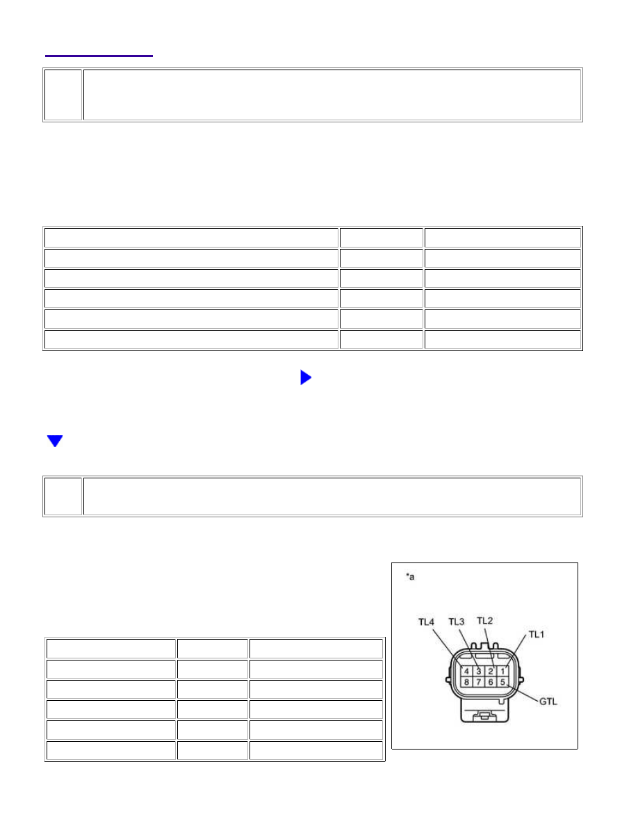
INSPECT TRANSFER SHIFT ACTUATOR ASSEMBLY (LIMIT SWITCH)

(a) Disconnect the D68 transfer shift actuator assembly

connector.

(b) Measure the resistance according to the value(s) in the table

below.

Standard Resistance:

TESTER CONNECTION

CONDITION

SPECIFIED CONDITION

1 (TL1) - Body ground

Always

10 kΩ or higher

2 (TL2) - Body ground

Always

10 kΩ or higher

3 (TL3) - Body ground

Always

10 kΩ or higher

4 (TL4) - Body ground

Always

10 kΩ or higher

5 (GTL) - Body ground

Always

10 kΩ or higher

WF1AM TRANSFER: TOUCH SELECT 2-4 AND HIGH-LOW SYS...

Text in Illustration

*a

Component without harness connected

(Transfer Shift Actuator Assembly)

NG

REPLACE TRANSFER SHIFT ACTUATOR ASSEMBLY

OK

REPLACE 4 WHEEL DRIVE CONTROL ECU

WF1AM TRANSFER: TOUCH SELECT 2-4 AND HIGH-LOW SYS...

Last Modified: 9-16-2014

6.6 C

Doc ID: RM000005KPW001X

Model Year: 2015

Model: Tundra

Prod Date Range: [08/2014 -           ]

Title: WF1AM TRANSFER: TOUCH SELECT 2-4 AND HIGH-LOW SYSTEM: P17AC; Transfer Shift Motor Limit

Switch Circuit; 2015 MY Tundra [08/2014 -        ]

DTC

P17AC

Transfer Shift Motor Limit Switch Circuit

DESCRIPTION

DTC

CODE

DTC DETECTION CONDITION

DIAGNOSIS CONDITION

1. 

MALFUNCTION STATUS

2. 

MALFUNCTION TIME

3. 

OTHER

4. 

TROUBLE AREA

P17AC

When the ignition switch is ON, the engine is running, and the

driving mode is being switched

1. 

switching order is abnormal

2. 

0.02 seconds or more

3. 

1 trip detection logic

4. 

Wire harness and

connector

4 wheel drive

control ECU

Transfer shift

actuator

assembly

WIRING DIAGRAM

Refer to DTC P17AB 


.

INSPECTION PROCEDURE

PROCEDURE

1.

CHECK HARNESS AND CONNECTOR (4 WHEEL DRIVE CONTROL ECU - TRANSFER SHIFT
ACTUATOR ASSEMBLY)

(a) Disconnect the A26 4 wheel drive control ECU connector.

(b) Disconnect the D68 transfer shift actuator assembly connector.

(c) Measure the resistance according to the value(s) in the table below.

Standard Resistance:

TESTER CONNECTION

CONDITION SPECIFIED CONDITION

A26-18 (TL1) - D68-1 (TL1)

Always

Below 1 Ω

WF1AM TRANSFER: TOUCH SELECT 2-4 AND HIGH-LOW SYS...

OK

TESTER CONNECTION

CONDITION SPECIFIED CONDITION

A26-20 (TL2) - D68-2 (TL2)

Always

Below 1 Ω

A26-26 (TL3) - D68-3 (TL3)

Always

Below 1 Ω

A26-24 (TL4) - D68-4 (TL4)

Always

Below 1 Ω

A26-22 (GTL) - D68-5 (GTL)

Always

Below 1 Ω

A26-18 (TL1) or D68-1 (TL1) - Body ground

Always

10 kΩ or higher

A26-20 (TL2) or D68-2 (TL2) - Body ground

Always

10 kΩ or higher

A26-26 (TL3) or D68-3 (TL3) - Body ground

Always

10 kΩ or higher

A26-24 (TL4) or D68-4 (TL4) - Body ground

Always

10 kΩ or higher

A26-18 (TL1) - D68-2 (TL2), D68-3 (TL3), D68-4 (TL4) and D68-5 (GTL)

Always

10 kΩ or higher

A26-20 (TL2) - D68-1 (TL1), D68-3 (TL3), D68-4 (TL4) and D68-5 (GTL)

Always

10 kΩ or higher

A26-26 (TL3) - D68-1 (TL1), D68-2 (TL2), D68-4 (TL4) and D68-5 (GTL)

Always

10 kΩ or higher

A26-24 (TL4) - D68-1 (TL1), D68-2 (TL2), D68-3 (TL3) and D68-5 (GTL)

Always

10 kΩ or higher

NG

REPAIR OR REPLACE HARNESS OR CONNECTOR

2.

CHECK 4 WHEEL DRIVE CONTROL ECU (ECU OUTPUT VOLTAGE)

(a) Disconnect the transfer shift actuator assembly connector.

(b) Measure the voltage according to the value(s) in the table

below.

Standard Voltage:

TESTER CONNECTION

SWITCH

CONDITION

SPECIFIED

CONDITION

D68-1 (TL1) - Body

ground

Ignition switch ON

4 to 6 V

D68-2 (TL2) - Body

ground

Ignition switch ON

4 to 6 V

D68-3 (TL3) - Body

ground

Ignition switch ON

4 to 6 V

D68-4 (TL4) - Body

ground

Ignition switch ON

4 to 6 V

Text in Illustration

WF1AM TRANSFER: TOUCH SELECT 2-4 AND HIGH-LOW SYS...


Content   ..  1003  1004  1005  1006   ..