Toyota Tundra (2015 year). Manual - part 28


  Index      Toyota     Toyota Tundra (2015 year) - Service and Repair Manual


Search            copyright infringement  


Content   ..  26  27  28  29   ..


Toyota Tundra (2015 year). Manual - part 28


Last Modified: 9-16-2014

6.6 A

Doc ID: RM00000334N00VX

Model Year: 2015

Model: Tundra

Prod Date Range: [08/2014 -           ]

Title: AUDIO / VISUAL: REAR DOOR SPEAKER (for CrewMax): REMOVAL; 2015 MY Tundra [08/2014 -        ]

REMOVAL

HINT:

Use the same procedure for the RH and LH sides.
The procedure listed below is for the LH side.

1. REMOVE REAR DOOR FRAME GARNISH LH 

2. REMOVE REAR DOOR INSIDE HANDLE BEZEL PLUG LH 

3. REMOVE REAR UPPER DOOR ARMREST BASE PANEL LH 

4. REMOVE REAR DOOR ARMREST COVER LH

5. REMOVE REAR DOOR TRIM BOARD SUB-ASSEMBLY LH 

6. REMOVE REAR NO. 1 SPEAKER ASSEMBLY

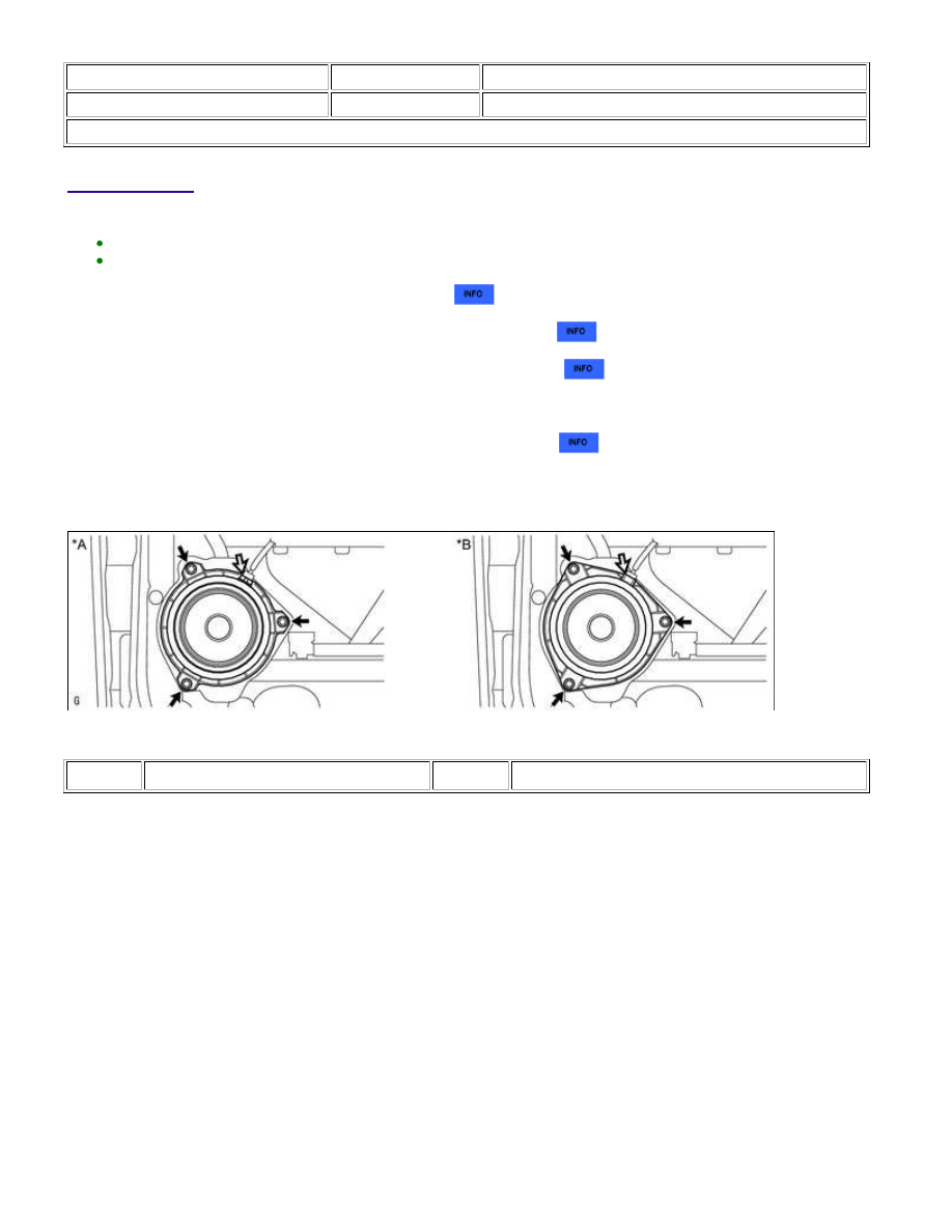
(a) Remove the 3 screws.

Text in Illustration

*A

for Standard

*B

for 12 Speakers

NOTICE:

7. REMOVE REAR NO. 2 SPEAKER ASSEMBLY

AUDIO / VISUAL: REAR DOOR SPEAKER (for CrewMax): REMOV...

Text in Illustration

*A

for Standard

*B

for 12 Speakers

(a) Detach the 3 claws and remove the rear No. 2 speaker assembly.

AUDIO / VISUAL: REAR DOOR SPEAKER (for CrewMax): REMOV...

Last Modified: 9-16-2014

6.6 G

Doc ID: RM00000334L00TX

Model Year: 2015

Model: Tundra

Prod Date Range: [08/2014 -           ]

Title: AUDIO / VISUAL: REAR DOOR SPEAKER (for CrewMax): INSPECTION; 2015 MY Tundra [08/2014 -        ]

INSPECTION

1. INSPECT REAR NO. 1 SPEAKER ASSEMBLY (for

Standard)

(a) Measure the resistance according to the value(s) in the table

below.

Standard resistance:

TESTER CONNECTION

CONDITION

SPECIFIED CONDITION

1 - 2

Always

2 Ω

If the result is not as specified, replace the rear No. 1 speaker

assembly.

Text in Illustration

*a

Component without harness connected

(Rear No. 1 Speaker Assembly)

2. INSPECT REAR NO. 1 SPEAKER ASSEMBLY (for 12

Speakers)

(a) Measure the resistance according to the value(s) in the table

below.

Standard resistance:

TESTER CONNECTION

CONDITION

SPECIFIED CONDITION

1 - 2

Always

1.8 to 2.6 Ω

If the result is not as specified, replace the rear No. 1 speaker

assembly.

Text in Illustration

*a

Component without harness connected

(Rear No. 1 Speaker Assembly)

3. INSPECT REAR NO. 2 SPEAKER ASSEMBLY

(a) When there is a malfunction such as noise from a speaker or no sound at all, replace the speaker with a

new one and check that the malfunction disappears.

OK:

Malfunction disappears.

AUDIO / VISUAL: REAR DOOR SPEAKER (for CrewMax): INSPE...

HINT:

Connect the connectors to the rear No. 2 speaker assemblies.
When there is a possibility that either the right or left rear No. 2 speaker assembly is defective, inspect by
interchanging the right one with the left one.
Perform the inspection above on both the LH and RH sides.

AUDIO / VISUAL: REAR DOOR SPEAKER (for CrewMax): INSPE...


Content   ..  26  27  28  29   ..