Subaru Legacy IV (2008 year). Manual - part 882


  Index      Subaru     Subaru Legacy IV - service repair manual 2008 year


Search            


Content   ..  880  881  882  883   ..


Subaru Legacy IV (2008 year). Manual - part 882


DI-77

Rear Differential (VA-type)

DIFFERENTIALS

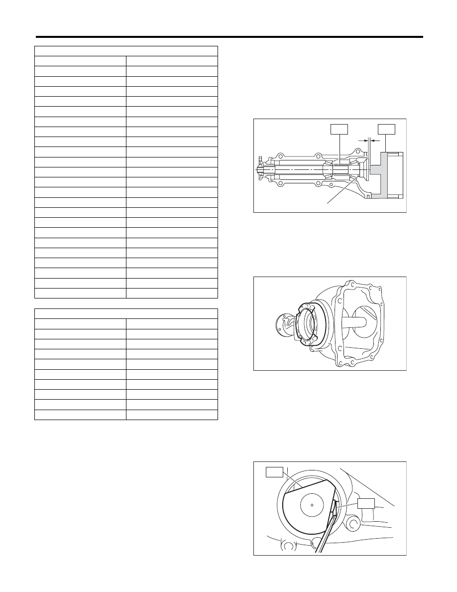
2) Adjusting drive pinion height:
Adjust the drive pinion height with washer installed
between the rear bearing cone and the back of pin-
ion gear.

(1) Attach ST2.

ST1

18678AA000 DUMMY SHAFT

ST2

18831AA010 DIFFERENTIAL CARRIER 

GAUGE

(2) Install the side retainer LH to the left side of
the differential carrier in the reverse direction.

(3) Measure the clearance “N” between the end
of ST2 and the end surface of ST1 by using a
thickness gauge.

NOTE:
Make sure there is no clearance between the case
and ST2.
ST1

18678AA000 DUMMY SHAFT

ST2

18831AA010 DIFFERENTIAL CARRIER 

GAUGE

Preload adjusting washer

Part No.

Thickness mm (in)

38336AA430

1.500 (0.0591)

38336AA440

1.513 (0.0596)

38336AA450

1.525 (0.0600)

38336AA460

1.538 (0.0606)

38336AA470

1.550 (0.0610)

38336AA480

1.563 (0.0615)

38336AA490

1.575 (0.0620)

38336AA500

1.588 (0.0625)

38336AA510

1.600 (0.0630)

38336AA520

1.613 (0.0635)

38336AA530

1.625 (0.0640)

38336AA540

1.638 (0.0645)

38336AA550

1.650 (0.0650)

38336AA560

1.663 (0.0655)

38336AA570

1.675 (0.0659)

38336AA580

1.688 (0.0665)

38336AA590

1.700 (0.0669)

38336AA600

1.713 (0.0674)

38336AA610

1.725 (0.0679)

38336AA620

1.738 (0.0684)

38336AA630

1.750 (0.0689)

38336AA640

1.763 (0.0694)

38336AA650

1.775 (0.0699)

Preload adjusting spacer

Part No.

Length mm (in)

31454AA250

51.05 (2.010)

31454AA260

51.25 (2.018)

31454AA270

51.35 (2.022)

31454AA280

51.45 (2.026)

31454AA290

51.55 (2.030)

31454AA300

51.65 (2.033)

31454AA310

51.75 (2.037)

31454AA320

51.85 (2.041)

31454AA330

52.05 (2.049)

N Measured value

(A) Pinion height adjusting washer

RH

LH

N

(A)

ST2

ST1

DI-00379

DI-00380

DI-00381

ST2

ST1

DI-78

Rear Differential (VA-type)

DIFFERENTIALS

(4) Obtain the thickness of pinion height adjust-
ing washer to be inserted from the following for-
mula, and replace the temporarily installed
washer with this one.

NOTE:
Adjust it using 1 — 3 washers.
T = To + N – 0.05 mm (0.002 in)

(Example of calculation)
To = 0.15 mm (0.0059 in)
N = 0.1 mm (0.0039 in)
T = 0.15 mm (0.0059 in) + 0.1 mm (0.0039 in) –
0.05 mm (0.0020 in) = 0.2 mm (0.0079 in)
Result: Thickness = 0.2 mm (0.0079 in)
Therefore use part number 32295AA370.

3) Install the selected pinion height adjusting wash-
er on drive pinion, and press the rear bearing cone
into position with ST.
ST

398177700

INSTALLER

4) Insert the drive pinion into the differential carrier,
and install the preselected bearing preload adjust-
ing spacer and washer.

5) Set ST and differential carrier to the press and
install the front bearing cone.
ST

399780104

WEIGHT

NOTE:
Set the carrier to the press until the companion
flange is installed.
6) Insert the spacer, then install the pilot bearing.

T

Thickness of pinion height adjusting 
washer mm (in)

To

Thickness of washer temporarily 
inserted mm (in)

N

Clearance of thickness gauge mm (in)

Memo:

Pinion height adjusting washer

Part No.

Thickness mm (in)

32295AA350

0.150 (0.0059)

32295AA360

0.175 (0.0069)

32295AA370

0.200 (0.0079)

32295AA380

0.225 (0.0089)

32295AA390

0.250 (0.0098)

32295AA400

0.275 (0.0108)

ST

DI-00085

(A) Drive pinion

(B) Bearing preload adjusting spacer

(C) Bearing preload adjusting washer

(D) Differential carrier

(A) Pilot bearing

(B) Spacer

(D)

(A)

(B)

(C)

DI-00382

ST

DI-00383

DI-00389

(A)

(B)

DI-79

Rear Differential (VA-type)

DIFFERENTIALS

7) Fit a new oil seal with ST.

NOTE:
• Press-fit until the oil seal end comes 1 mm (0.04
in) inward from end of carrier.
• Apply the differential gear oil to the oil seal lips.
ST

499277200

INSTALLER

8) Press-fit the companion flange with ST.

NOTE:
Be careful not to damage the bearing.
ST

899874100

INSTALLER

9) Apply seal material on the drive pinion shaft
thread and new self-locking nut seat.

SEAL MATERIAL:

THREE BOND 1324 (Part No. 004403042) or 
equivalent

10) Tighten the nut and use the ST to fix the com-
panion flange in place, then tighten.
ST

498427200

FLANGE WRENCH

Tightening torque:

191 N·m (19.5 kgf-m, 140.9 ft-lb)

11) Measure the initial torque and initial load.

Initial load:

12.7 — 32.2 N (1.3 — 3.3 kgf, 2.9 — 7.2 lb)

Initial torque:

0.48 — 1.22 N·m 
(0.05 — 0.12 kgf-m, 0.35 — 0.90 ft-lb)

12) Install the hypoid driven gear to differential
case.

NOTE:
• Set a cushioning such as wooden block, alumi-
num plate or shop cloth between vise and differen-
tial case if the side gear comes into contact with
vise.
• Before installing bolts, apply seal material to bolt
threads.

SEAL MATERIAL:

THREE BOND 1324 (Part No. 004403042)

• Tighten diagonally.

Tightening torque:

62 N·m (6.3 kgf-m, 45.7 ft-lb)

ST

DI-00089

DI-00384

ST

DI-00372

ST

DI-00152

DI-00481

DI-00371

DI-80

Rear Differential (VA-type)

DIFFERENTIALS

13) Press the side bearing into differential case us-
ing ST.
ST

398487700

DRIFT

14) Assemble the side retainer.

(1) Attach the new oil seal to the side retainer
RH and LH.

ST

498447100

INSTALLER

(2) Attach the bearing race to side retainer RH
and LH.

ST

398417700

DRIFT

CAUTION:
Be careful to properly match the RH and LH oil
seals, bearing outer races and cones during as-
sembly.

(3) Install the differential assembly into differen-
tial carrier in the reverse order of disassembly.

NOTE:
Be careful not to hit the teeth against the case.

(4) Push the side retainer RH and LH lightly into
the differential carrier to install.

15) Perform the backlash adjustment between the
hypoid driven gear and drive pinion, and preload
adjustment of differential side bearing.

(1) Turn the drive pinion with ST for better fitting
of differential side bearing.

ST

498427200

FLANGE WRENCH

(2) Using the ST, tighten the side retainer LH,
and then tighten the side retainer RH until there
is no backlash.

ST

18630AA010

WRENCH COMPL 
RETAINER

(3) Back off the side retainer LH by approx. 1.5
teeth, and tighten the side retainer RH by ap-
prox. 2 teeth (amount that the side retainer LH
is turned back (1.5) + 1/2 teeth).
Difference between [amount that the side re-
tainer LH is turned back (approx. 1 and 1/2
teeth)] and [amount that the side retainer RH is
tightened (approx. 2 teeth)] gives preload.
(4) Temporarily tighten the lock plate.

NOTE:
Turn over the lock plate to shift the holder by 0.5
teeth.

ST

DI-00095

ST

DI-00166

DI-00366

DI-00385

ST

ST

DI-00399

DI-00364


Content   ..  880  881  882  883   ..