Subaru Legacy IV (2008 year). Manual - part 883


  Index      Subaru     Subaru Legacy IV - service repair manual 2008 year


Search            


Content   ..  881  882  883  884   ..


Subaru Legacy IV (2008 year). Manual - part 883


DI-81

Rear Differential (VA-type)

DIFFERENTIALS

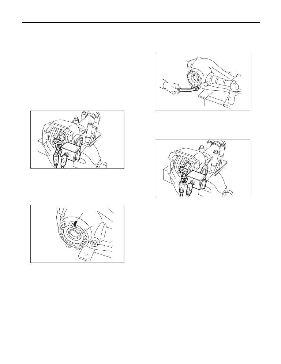
(5) Measure the hypoid driven gear-to-drive
pinion backlash. Set the magnet base on differ-
ential carrier. Align the contact point of dial
gauge with tooth face of hypoid driven gear,
and move hypoid driven gear while holding
drive pinion still. Read the value indicated on
dial gauge.

NOTE:
If measured value of backlash is not within the
specified range, repeat the procedures for pinion
driven gear set backlash adjustment and the differ-
ential side bearing preload adjustment.

Backlash:

0.10 — 0.15 mm (0.004 — 0.006 in)

16) Mark both the differential carrier and side re-
tainer with alignment marks. Remove the side re-
tainer one side at a time.
Replace them in the original position after inserting
an O-ring and applying differential gear oil to the
threaded portion.

17) Tighten the bolt of lock plate to specified
torque.

Tightening torque:

25 N·m (2.5 kgf-m, 18.4 ft-lb)

18) Recheck the hypoid driven gear to pinion back-
lash.

Backlash:

0.10 — 0.15 mm (0.004 — 0.006 in)

19) Checking and adjusting the tooth contact of hy-
poid driven gear

(1) Apply lead-free red dye evenly on the both
sides of three to four teeth of the hypoid driven
gear. Check the contact pattern after rotating
the hypoid driven gear several revolutions back
and forth until a definite contact pattern appears
on the hypoid driven gear.
(2) When the contact pattern is not correct, re-
adjust.

NOTE:
Be sure to wipe off the lead-free red dye completely
after the adjustment is completed.

(A) Alignment mark

(B) Side retainer

DI-00172

DI-00386

(B)

(A)

DI-00364

DI-00172

DI-82

Rear Differential (VA-type)

DIFFERENTIALS

• Correct tooth contact
Check item: Tooth contact pattern is slightly
shifted towards the toe side under no-load
rotation. (When driving, it moves towards
the heel side.)

• Face contact
Check item: Backlash is too large.
Contact pattern

Corrective action: Increase thickness of drive
pinion height adjusting washer in order to bring
drive pinion close to hypoid driven gear.

• Flank contact
Check item: Backlash is too small.
Contact pattern

Corrective action: Reduce the thickness of pin-
ion height adjusting washer according to the
procedure for bringing drive pinion away from
hypoid driven gear.

• Toe contact (inside contact)
Check item: Contact area is too small.
Contact pattern

Corrective action: Reduce the thickness of pin-
ion height adjusting washer according to the
procedure for bringing drive pinion away from
hypoid driven gear.

(A) Toe side

(B) Heel side

(A)

(B)

MT-01401

AT-00208

AT-00212

AT-00209

AT-00213

AT-00210

AT-00213

DI-83

Rear Differential (VA-type)

DIFFERENTIALS

• Heel contact (outside end contact)
Check item: Contact area is too small.
Contact pattern

Corrective action: Increase thickness of drive
pinion height adjusting washer in order to bring
drive pinion close to hypoid driven gear.

20) If correct tooth contact is not obtained, once
again adjust the drive pinion height and the differ-
ential side bearing preload (already mentioned)
and the hypoid gear backlash.
21) Install the new gasket and rear cover to the dif-
ferential carrier, and tighten the bolts to specified
torque.

Tightening torque:

34 N·m (3.5 kgf-m, 25.1 ft-lb)

22) Install the air breather cap.

NOTE:
When installing the air breather cap, hit on section
(A). Be sure to hit on section (B) to install.

23) Tighten the oil drain plug and filler plug.

Tightening torque:

50 N·m (5.1 kgf-m, 36.9 ft-lb)

E: INSPECTION

Wash all the disassembled parts clean, and exam-
ine them for wear, damage or other defects. Repair
or replace the defective parts as necessary.
1) Hypoid driven gear and drive pinion
• If there is evidently an abnormal tooth contact,
find out the cause and adjust until the teeth contact
correctly. Replace the gear if there is an excessive
worn or an incapable adjustment.
• If crack, cutout or seizure is found, replace the
parts as a set. Slight damage of some teeth can be
corrected by oil stone or the like.
2) Side gear and pinion mate gear
• Replace if cracks, scoring or other defects are
evident on the tooth surface.
• Replace if thrust washer contact surface is worn
or seized. Slight damages of the surface can be
corrected by oil stones or equivalent.
3) Bearing
Replace if seizure, peeling, wear, rust, dragging
during rotation, noise or other defect is evident.
4) Thrust washer of the side gear and pinion mate
gear
Replace if seized, flawed, abnormally worn or hav-
ing other defects.
5) Oil seal
Replace if deformed or damaged, and at every dis-
assembling.
6) Differential carrier
Replace if the bearing bores are worn or damaged.
7) Differential case
Replace if its sliding surfaces are abnormally worn,
burned, or cracked.
8) Companion flange
Replace if the oil seal lip contact surface shows
cracking.

AT-00211

AT-00212

DI-00387

DI-00564

(A)

(B)

DI-84

Rear Differential (VA-type)

DIFFERENTIALS

1. SIDE GEAR BACKLASH

Using a dial gauge, check the backlash of side
gear. (VA1-type only)

Side gear backlash:

0.05 — 0.15 mm (0.002 — 0.006 in)

If the side gear backlash is not within the specifica-
tion, select the side gear thrust washer and adjust
the side gear backlash as specified.

2. HYPOID DRIVEN GEAR BACKLASH

Using a dial gauge, check the backlash of hypoid
driven gear.

Hypoid driven gear backlash:

0.10 — 0.15 mm (0.004 — 0.006 in)

If the hypoid driven gear backlash is not within the
specification, adjust the side bearing preload or re-
pair if necessary.

3. TOOTH CONTACT BETWEEN HYPOID 
DRIVEN GEAR AND DRIVE PINION

Inspect the tooth contact between the hypoid driv-
en gear and drive pinion. <Ref. to DI-66, ASSEM-
BLY, Rear Differential (VA-type).>

4. COMPANION FLANGE

1) If rust or dirt is attached to the companion flange,
remove them.
2) Set a dial gauge at a companion flange surface
(mating surface of propeller shaft and companion
flange), and then measure the companion flange
runout.

Limit of runout:

0.08 mm (0.003 in)

3) Set the gauge inside of the companion flange,
and measure the runout.

Limit of runout:

0.08 mm (0.003 in)

4) If either runout exceeds the limit, move the
phase of companion flange and drive pinion 90°
each, and find the point where the runout is within
the limit.
5) If the runout exceeds the limit even after chang-
ing the phase, replace the companion flange and
recheck the runout.
6) If the runout exceeds the limit after replacing the
companion flange, the drive pinion may be assem-
bled incorrectly or bearing is faulty.

DI-00240

DI-00099

DI-00360

DI-00361


Content   ..  881  882  883  884   ..