Subaru Legacy IV (2008 year). Manual - part 880


  Index      Subaru     Subaru Legacy IV - service repair manual 2008 year


Search            


Content   ..  878  879  880  881   ..


Subaru Legacy IV (2008 year). Manual - part 880


DI-69

Rear Differential (VA-type)

DIFFERENTIALS

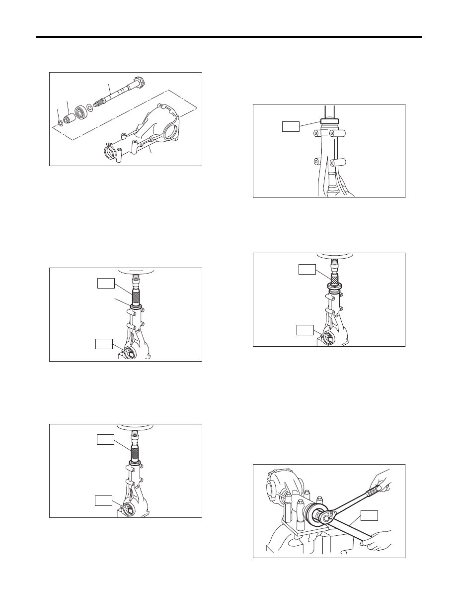
4) Insert the drive pinion into the differential carrier,
and install the preselected bearing preload adjust-
ing spacer and washer.

5) Press-fit the front bearing cone into the carrier
with ST1, ST2 and the spacer.
ST1

399780104

WEIGHT

ST2

899580100

INSTALLER

Part No.

32285AA000   Spacer

6) Insert the spacer, then press-fit the pilot bearing
with ST1 and ST2.
ST1

399780104

WEIGHT

ST2

899580100

INSTALLER

7) Fit a new oil seal with ST.

NOTE:
• Press-fit until the oil seal end comes 1 mm (0.04
in) inward from end of carrier.
• Apply the differential gear oil to the oil seal lips.
ST

498447120

INSTALLER

8) Press-fit the companion flange with ST1 and ST2.

NOTE:
Be careful not to damage the bearing.
ST1

899874100

INSTALLER

ST2

399780104

WEIGHT

9) Attach a new self-locking nut and secure the
companion flange using ST, then tighten the nut.

NOTE:
Before installing lock nuts, apply seal material to
lock nut threads.

SEAL MATERIAL:

THREE BOND 1324 (Part No. 004403042) or 
equivalent

ST

498427200

FLANGE WRENCH

Tightening torque:

191 N·m (19.5 kgf-m, 140.9 ft-lb)

(A) Drive pinion

(B) Bearing preload adjusting spacer

(C) Bearing preload adjusting washer

(D) Differential carrier

(A) Spacer (SUBARU genuine part)

(D)

(A)

(B)

(C)

DI-00156

DI-00468

ST2

ST1

(A)

ST2

ST1

DI-00088

ST

DI-00089

ST1

ST2

DI-00090

ST

DI-00161

DI-70

Rear Differential (VA-type)

DIFFERENTIALS

10) Check the initial torque and initial load.

Initial load:

12.7 — 32.2 N (1.3 — 3.3 kgf, 2.9 — 7.2 lb)

Initial torque:

0.48 — 1.22 N·m 
(0.05 — 0.12 kgf-m, 0.35 — 0.90 ft-lb)

11) Assembling differential case
Install the side gears and pinion mate gears, with
their thrust washers and pinion mate shaft, into the
differential case.

NOTE:
• Apply gear oil on both sides of the washer and on
the side gear shaft before installing.
• Insert the pinion mate shaft into the differential
case by aligning the lock pin holes.

(1) Measure the side gear backlash.

Side gear backlash:

0.05 — 0.15 mm (0.002 — 0.006 in)

(2) Adjust the side gear backlash as specified
by selecting side gear thrust washer.

DI-00152

DI-00481

Side gear thrust washer

Part No.

Thickness mm (in)

803135011

0.925 — 0.950 (0.0364 — 0.0374)

803135012

0.950 — 0.975 (0.0374 — 0.0384)

803135013

0.975 — 1.000 (0.0384 — 0.0394)

803135014

1.000 — 1.025 (0.0394 — 0.0404)

803135015

1.025 — 1.050 (0.0404 — 0.0413)

DI-00239

DI-00240

DI-71

Rear Differential (VA-type)

DIFFERENTIALS

(3) Check the condition of rotation after apply-
ing oil to the gear tooth surfaces and thrust sur-
faces.
(4) After inserting the pinion shaft lock pin into
differential case, stake the both sides of the
hole to prevent pin from falling off.

12) Install the hypoid driven gear to differential
case.

NOTE:
• Before installing bolts, apply seal material to bolt
threads.

SEAL MATERIAL:

THREE BOND 1324 (Part No. 004403042) or 
equivalent

• Tighten diagonally.

Tightening torque:

62 N·m (6.3 kgf-m, 45.7 ft-lb)

13) Press the side bearing into differential case us-
ing ST.
ST

498485400

DRIFT

14) Assemble the side retainer.

(1) Attach the oil seal to the side retainer RH
and LH.

ST

498447100

INSTALLER

(2) Attach the bearing race to side retainer RH
and LH.

ST

398477702

DRIFT

CAUTION:
Be careful to properly match the RH and LH oil
seals, bearing outer races and cones during as-
sembly.

(3) Install the differential assembly into differen-
tial carrier in the reverse order of disassembly.

NOTE:
Be careful not to hit the teeth against the case.

(4) Push the side retainer RH and LH lightly into
the differential carrier to install.

DI-00068

ST

DI-00095

ST

DI-00166

ST

DI-00167

DI-00134

DI-72

Rear Differential (VA-type)

DIFFERENTIALS

15) Perform the backlash adjustment between the
hypoid driven gear and drive pinion, and preload
adjustment of differential side bearing.

(1) Turn the drive pinion with ST for better fitting
of differential side bearing.

ST

498427200

FLANGE WRENCH

(2) Using the ST, tighten side retainer RH, and
then tighten side retainer LH until there is no
backlash.

ST

18630AA010

WRENCH COMPL 
RETAINER

(3) Back off the side retainer LH by approx. 1.5
teeth, and tighten the side retainer RH by ap-
prox. 2 teeth (amount that the side retainer LH
is turned back (1.5) + 1/2 teeth).
Difference between [amount that the side re-
tainer LH is turned back (approx. 1 and 1/2
teeth)] and [amount that the side retainer RH is
tightened (approx. 2 teeth)] gives preload.
(4) Temporarily tighten the lock plate.

NOTE:
Turn over the lock plate to shift the holder by 1/2
tooth.

(5) Measure the hypoid driven gear-to-drive
pinion backlash. Set the magnet base on differ-
ential carrier. Align the contact point of dial
gauge with tooth face of hypoid driven gear,
and move hypoid driven gear while holding
drive pinion still. Read the value indicated on
dial gauge.

NOTE:
If measured value of backlash is not within the
specified range, repeat the procedures for pinion
driven gear set backlash adjustment and the differ-
ential side bearing preload adjustment.

Backlash:

0.10 — 0.15 mm (0.004 — 0.006 in)

16) Mark both the differential carrier and side re-
tainer with alignment marks. Remove the side re-
tainer one side at a time.
Replace them in the original position after inserting
an O-ring and applying gear oil to the threaded por-
tion.

ST

DI-00169

DI-00133

ST

DI-00132

(A) Alignment mark

(B) Side retainer

DI-00172

(A)

(B)

DI-00173


Content   ..  878  879  880  881   ..