Subaru Legacy IV (2008 year). Manual - part 879


  Index      Subaru     Subaru Legacy IV - service repair manual 2008 year


Search            


Content   ..  877  878  879  880   ..


Subaru Legacy IV (2008 year). Manual - part 879


DI-65

Rear Differential (VA-type)

DIFFERENTIALS

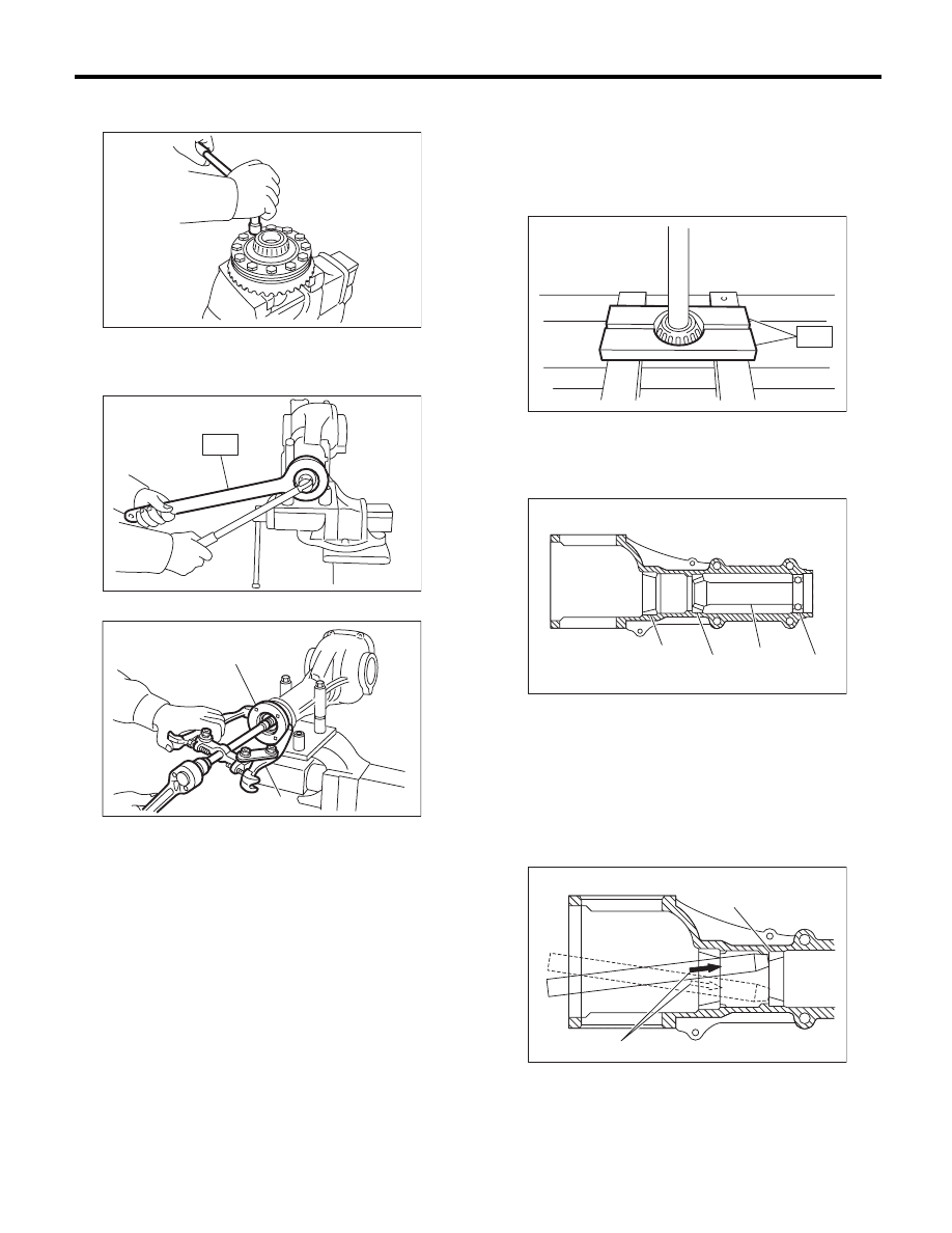
11) Remove the hypoid driven gear by loosening
hypoid driven gear bolts.

12) Remove the self-locking nut while holding the
companion flange with ST.
ST

498427200

FLANGE WRENCH

13) Extract the companion flange with a puller.

14) Removes the drive pinion shaft.

15) Remove the rear bearing cone from drive pin-
ion by supporting the cone with ST.

NOTE:
Place the replacer so that its center-recessed side
faces the pinion gear.
ST

398517700

REPLACER

16) Remove the front oil seal from differential carri-
er using screwdriver.
17) Remove the pilot bearing, front bearing cone
and spacer.

18) When replacing the bearings, hit out the front
bearing cup and rear bearing cup in this order using
a brass bar.

(A) Companion flange

(B) Puller

DI-00371

DI-00372

ST

(B)

(A)

DI-00394

(A) Pilot bearing

(B) Spacer

(C) Front bearing

(D) Rear bearing cup

(A) 2 cutout portions along diagonal lines

(B) Tap alternately with brass bar.

DI-00373

ST

(B)

(A)

(C)

(D)

DI-00374

(B)

(A)

DI-00077

DI-66

Rear Differential (VA-type)

DIFFERENTIALS

D: ASSEMBLY

1. VA1-TYPE

NOTE:
• Assemble in the reverse order of disassembly.
• Check and adjust each part during assembly.
• Use new gaskets and O-rings.
• Keep the shims and washers in order, so that
they are not improperly installed.
• Thoroughly clean the surfaces on which the
shims, washers and bearings are to be installed.
• Apply gear oil when installing the bearings and
thrust washers.
• Be careful not to mix up the RH and LH bearing
races.
• Replace the oil seals and O-rings with new parts
at every disassembly.
• Apply differential gear oil to the lips when install-
ing the oil seal.
• Be careful not to mix up the differential oil seal
RH and LH.

1) Adjusting preload for front and rear bearings

NOTE:
Adjust the bearing preload between front and rear
bearings with spacer and washer. Pinion height ad-
justing washer is not affected by this adjustment.
The adjustment must not be carried out with oil seal
inserted.

(1) Install the rear bearing race into the differen-
tial carrier using ST1 and ST2.

ST1

398477701

HANDLE

ST2

398477702

DRIFT

(2) Install the front bearing race to the differen-
tial carrier using ST1 and ST2.

ST1

398477701

HANDLE

ST2

498447110

DRIFT

(3) Insert the front bearing cone.

NOTE:
Use new front bearing cone.

(4) Measure and record the thickness of pinion
height adjusting washer.

NOTE:
If tooth contact (drive pinion and hypoid driven
gear) is normal in the inspection before disassem-
bling, verify that the washer is not deformed, and
then reuse the used washer.

(5) Insert ST1 into the case with the pinion
height adjusting washer and rear bearing cone
fitted onto it.

NOTE:
Use new rear bearing cone.

(6) Install the preload adjusting spacer & wash-
er, front bearing cone, ST2, companion flange,
and washer & self-locking nut.

ST

498447150

DUMMY SHAFT

Part No. 32285AA000   Spacer

DI-00078

DI-00149

ST2

ST1

(A) Pinion height adjusting washer

(B) Preload adjusting spacer

(C) Preload adjusting washer

(D) Spacer (SUBARU genuine part)

DI-00466

(B)

(A)

(C)

ST

(D)

DI-67

Rear Differential (VA-type)

DIFFERENTIALS

(7) Turn the ST1 by hand to smooth the bear-
ing, and tighten the self-locking nut while mea-
suring the initial load or initial torque with a
spring scale or torque wrench. Select the pre-
load adjusting washer and spacer so that the
specified preload is obtained when nut is tight-
ened to the specified torque.

NOTE:
• Use a new self-locking nut.
• Measure the preload in direction of tangent to the
flange.
• Be careful not to give excessive preload.
• When tightening the self-locking nut, lock ST1
with ST2 as shown in the figure.
ST1

498447150

DUMMY SHAFT

ST2

398507704

BLOCK

Tightening torque:

191 N·m (19.5 kgf-m, 140.9 ft-lb)

Initial load:

12.7 — 32.2 N (1.3 — 3.3 kgf, 2.9 — 7.2 lb)

Initial torque:

0.48 — 1.22 N·m 
(0.05 — 0.12 kgf-m, 0.35 — 0.9 ft-lb)

ST1

ST2

DI-00081

DI-00152

DI-00481

Preload adjusting washer

Part No.

Thickness mm (in)

38336AA000

1.500 (0.0591)

38336AA120

1.513 (0.0596)

38336AA010

1.525 (0.0600)

38336AA130

1.538 (0.0606)

38336AA020

1.550 (0.0610)

38336AA140

1.563 (0.0615)

38336AA030

1.575 (0.0620)

38336AA150

1.588 (0.0625)

38336AA040

1.600 (0.0630)

38336AA160

1.613 (0.0635)

38336AA050

1.625 (0.0640)

38336AA170

1.638 (0.0645)

38336AA060

1.650 (0.0650)

38336AA180

1.663 (0.0655)

38336AA070

1.675 (0.0659)

38336AA190

1.688 (0.0665)

38336AA080

1.700 (0.0669)

38336AA200

1.713 (0.0674)

38336AA090

1.725 (0.0679)

38336AA210

1.738 (0.0684)

38336AA100

1.750 (0.0689)

38336AA220

1.763 (0.0694)

38336AA110

1.775 (0.0699)

Preload adjusting spacer

Part No.

Length mm (in)

32288AA040

52.3 (2.059)

32288AA050

52.5 (2.067)

31454AA100

52.6 (2.071)

32288AA060

52.7 (2.075)

31454AA110

52.8 (2.079)

32288AA070

52.9 (2.083)

31454AA120

53.0 (2.087)

32288AA080

53.1 (2.091)

32288AA090

53.3 (2.098)

DI-68

Rear Differential (VA-type)

DIFFERENTIALS

2) Adjusting drive pinion height:
Adjust the drive pinion height with washer installed
between the rear bearing cone and the back of pin-
ion gear.

(1) Attach ST2.

NOTE:
At this time, install a provisionally selected or previ-
ously used pinion height adjusting washer.
ST1

498447150

DUMMY SHAFT

ST2

498505501

DIFFERENTIAL CARRIER 
GAUGE

Part No.

32285AA000   Spacer

(2) Measure the clearance “N” between the end
of ST2 and the end surface of ST1 by using a
thickness gauge.

NOTE:
Make sure there is no clearance between the case
and ST2.
ST1

498447150

DUMMY SHAFT

ST2

498505501

DIFFERENTIAL CARRIER 
GAUGE

(3) Obtain the thickness of pinion height adjust-
ing washer to be inserted from the following for-
mula, and replace the temporarily installed
washer with this one.

NOTE:
Adjust it using 1 — 3 washers.
T = To + N – 0.05 mm (0.0020 in)

(Example of calculation)
To = 0.15 mm (0.0059 in)
N = 0.1 mm (0.0039 in)
T = 0.15 mm (0.0059 in) + 0.1 mm (0.0039 in) –
0.05 mm (0.0020 in) = 0.2 mm (0.0079 in)
Result: Thickness = 0.2 mm (0.0079 in)
Therefore use part number 32295AA220.

3) Install the selected pinion height adjusting wash-
er on drive pinion, and press the rear bearing cone
into position with ST.
ST

498175500

INSTALLER

N Measured value

(A) Pinion height adjusting washer

(B) Spacer (SUBARU genuine part)

DI-00467

RH

LH

N

(A)

ST2

ST1

(B)

ST2

ST1

DI-00084

T

Thickness of pinion height adjusting 
washer mm (in)

To

Thickness of washer temporarily 
inserted mm (in)

N

Clearance of thickness gauge mm (in)

Memo:

Pinion height adjusting washer

Part No.

Thickness mm (in)

32295AA200

0.150 (0.0059)

32295AA210

0.175 (0.0069)

32295AA220

0.200 (0.0079)

32295AA230

0.225 (0.0089)

32295AA240

0.250 (0.0098)

32295AA250

0.275 (0.0108)

ST

DI-00085


Content   ..  877  878  879  880   ..