Subaru Legacy IV (2008 year). Manual - part 877
DI-57
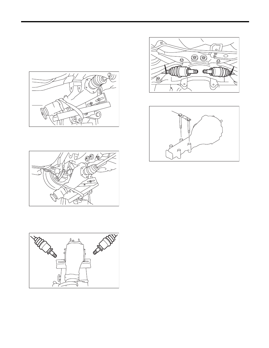
Rear Differential (VA-type)
DIFFERENTIALS
19) Remove the self-lock nuts which hold the rear
differential to rear crossmember.
20) Remove the rear differential stud bolt from rear
crossmember bushing.
NOTE:
When removing the stud bolt, carefully adjust the
angle and location of transmission jack and jack
stand, if necessary
21) Lower the transmission jack stand after remov-
ing the rear differential stud bolt from the rear
crossmember. Rear drive shaft should not come
into contact with the lateral link bolt.
22) Pull out the axle shaft from rear differential.
NOTE:
If it is difficult to remove the axle shaft from rear dif-
ferential, remove it using tire lever.
23) Lower the transmission jack.
24) Secure the rear drive shaft to lateral link using
wire.
25) Remove the rear differential member plate from
rear differential.
DI-00400
DI-00392
DI-00276
(A) Rear differential member plate
DI-00277
DI-00359
(A)