Subaru Legacy IV (2008 year). Manual - part 875


  Index      Subaru     Subaru Legacy IV - service repair manual 2008 year


Search            


Content   ..  873  874  875  876   ..


Subaru Legacy IV (2008 year). Manual - part 875


DI-49

Rear Differential (T-type)

DIFFERENTIALS

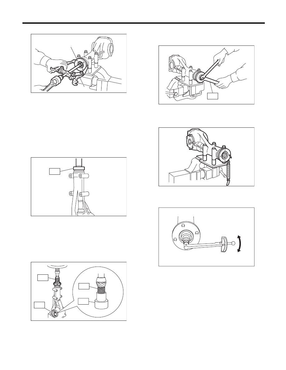
13) Draw out the companion flange with a puller.

14) Install a new oil seal using ST.

NOTE:
• Press-fit until the oil seal end comes 1 mm (0.04
in) inward from end of carrier.
• Apply the differential gear oil between the oil seal
lips.
ST

498447120

INSTALLER

15) Press-fit the companion flange with ST1, ST2
and ST3.
ST1

899874100

INSTALLER

ST2

399780104

WEIGHT

ST3

498937110

HOLDER DRIVE PINION

NOTE:
Be careful not to damage the bearing.

16) Install the self-locking nut. Tighten using the
ST.
ST

498427200

FLANGE WRENCH

17) Check the initial torque and initial load.

Initial load:

24.1 — 38.6 N (2.5 — 3.9 kgf, 5.4 — 8.7 lb)

Initial torque:

0.91 — 1.46 N·m 
(0.09 — 0.15 kgf-m, 0.67 — 1.08 ft-lb)

(A) Companion flange

(B) Puller

(B)

(A)

DI-00142

ST

DI-00089

ST3

ST1

ST2

ST2

DI-00323

ST

DI-00071

DI-00117

DI-00481

DI-50

Rear Differential (T-type)

DIFFERENTIALS

18) Install the driven gear to the differential case.

NOTE:
• Before installing bolts, apply seal material to bolt
threads.
• Tighten diagonally.

SEAL MATERIAL:

THREE BOND 1324 (Part No. 004403042) or 
equivalent

Tightening torque:

103 N·m (10.5 kgf-m, 76.0 ft-lb)

19) Press the side bearing into differential case us-
ing ST.
ST

398487700

DRIFT

20) Assembling the side retainer

(1) Using the ST and a press, press-fit the side
bearing outer race.

ST

398417700

DRIFT

(2) Install the oil seal. <Ref. to DI-88, RE-
PLACEMENT, Rear Differential Side Oil Seal.>

21) Adjusting side retainer shims

(1) The driven gear backlash and side bearing
preload can be adjusted by the side retainer
shim thickness.
(2) Install the differential case assembly into dif-
ferential carrier in the reverse order of disas-
sembly.

NOTE:
Be careful not to hit the teeth against the case.

(3) Install the side retainer shims and O-rings to
retainers RH and LH from which they were re-
moved.

NOTE:
• Replace the O-ring with a new part.
• Replace broken or corroded side retainer shims
with a new part of the same thickness.

(4) When installing, align the arrow mark on the
differential carrier with the mark on the side re-
tainer.

NOTE:
Be careful that side bearing outer race is not dam-
aged by the bearing roller.

DI-00068

ST

DI-00095

DI-00324

ST

Side retainer shim

Part No.

Thickness mm (in)

383475201

0.20 (0.0079)

383475202

0.25 (0.0098)

383475203

0.30 (0.0118)

383475204

0.40 (0.0157)

383475205

0.50 (0.0197)

(A) Arrow mark (Side retainer side)

(B) Arrow mark (Differential carrier side)

DI-00065

DI-00543

(B)

(A)

DI-51

Rear Differential (T-type)

DIFFERENTIALS

(5) Tighten the side retainer bolts.

Tightening torque:

10.5 N·m (1.1 kgf-m, 7.7 ft-lb)

(6) Measure the backlash between the hypoid
driven gear and drive pinion. Set the magnet
base on differential carrier. Align the contact
point of dial gauge with tooth face of hypoid
driven gear, and move hypoid driven gear while
holding drive pinion still. Read the value indicat-
ed on dial gauge. If the backlash is outside the
standard range, adjust the side retainer shim by
the following method.
• When backlash is less than 0.1 mm (0.004
in):
Reduce the hypoid driven gear back surface
shim thickness and increase the hypoid driven
gear tooth surface side shim thickness.
• When backlash exceeds 0.2 mm (0.008
in):
Increase the thickness of shim on the back side
of the hypoid driven gear and reduce the thick-
ness of shims on the teeth side of the hypoid
driven gear.

Backlash:

0.10 — 0.20 mm (0.004 — 0.008 in)

(7) At the same time, measure the total preload
of the drive pinion. Compared with when differ-
ential case is not installed, if the total preload is
not within specification, adjust the thickness of
side retainer shims, by increasing/reducing
both shims by an even amount at a time.

Total preload:

27.0 — 54.0 N (2.8 — 5.5 kgf, 6.1 — 12.1 lb)

22) Measure the backlash between the hypoid driv-
en gear and drive pinion again.

Backlash:

0.10 — 0.20 mm (0.004 — 0.008 in)

23) Check the hypoid driven gear runout on its
back surface, and make sure that the pinion and
hypoid driven gear rotates smoothly.
If the hypoid driven gear runout on its rear face ex-
ceeds the limit, check for any foreign objects be-
tween hypoid driven gear and differential case, and
for any deformation of the case or gear.

Driven gear rear face runout limit:

0.05 mm (0.002 in)

24) Checking and adjusting the tooth contact of hy-
poid driven gear

(1) Apply lead-free red dye evenly on the both
sides of three to four teeth of the hypoid driven
gear. Rotate the hypoid driven gear several rev-
olutions back and forth until a definite contact
pattern appears on the hypoid driven gear, and
check the contact pattern.

DI-00487

DI-00099

DI-00099

DI-00101

DI-52

Rear Differential (T-type)

DIFFERENTIALS

(2) When the contact pattern is not correct, re-
adjust.

NOTE:
Be sure to wipe off the lead-free red dye after the
adjustment is completed.

• Correct tooth contact
Check item: Tooth contact pattern is slightly
shifted towards the toe side under no-load
rotation. (When driving, it moves towards
the heel side.)

• Face contact
Check item: Backlash is too large.
Contact pattern

Corrective action: Increase thickness of drive
pinion height adjusting washer in order to bring
drive pinion close to hypoid driven gear.

• Flank contact
Check item: Backlash is too small.
Contact pattern

Corrective action: Reduce the thickness of pin-
ion height adjusting washer according to the
procedure for bringing drive pinion away from
hypoid driven gear.

• Toe contact (inside contact)
Check item: Contact area is too small.
Contact pattern

Corrective action: Reduce the thickness of pin-
ion height adjusting washer according to the
procedure for bringing drive pinion away from
hypoid driven gear.

(A) Toe side

(B) Heel side

(A)

(B)

MT-01401

AT-00208

AT-00212

AT-00209

AT-00213

AT-00210

AT-00213


Content   ..  873  874  875  876   ..