Subaru Legacy IV (2008 year). Manual - part 842


  Index      Subaru     Subaru Legacy IV - service repair manual 2008 year


Search            


Content   ..  840  841  842  843   ..


Subaru Legacy IV (2008 year). Manual - part 842


FS-15

Front Stabilizer

FRONT SUSPENSION

4. Front Stabilizer

A: REMOVAL

1) Lift up the vehicle, and then remove the front
wheels.
2) Remove the front under cover. <Ref. to EI-26,
REMOVAL, Front Under Cover.>
3) Remove the front crossmember support plate.
<Ref. to FS-14, REMOVAL, Front Crossmember
Support Plate.>
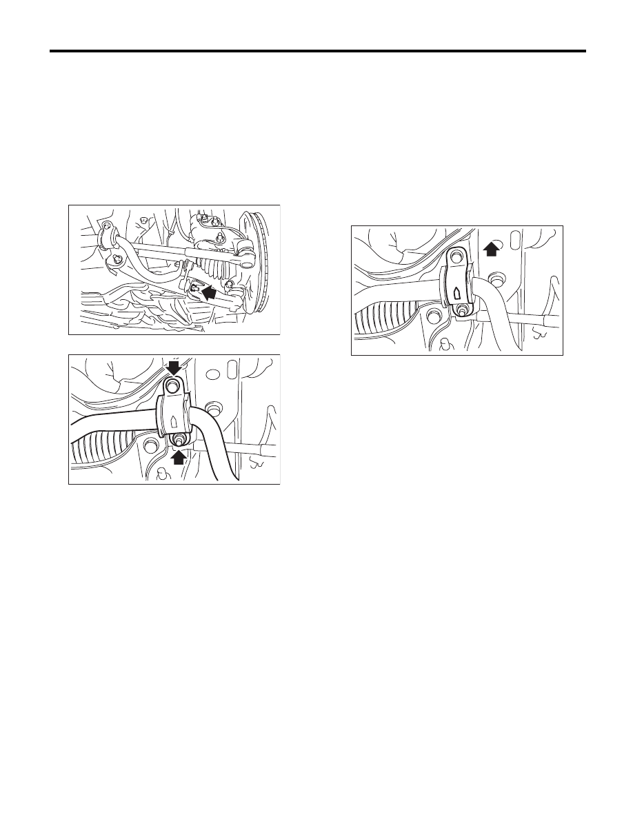
4) Remove the stabilizer link.

5) Remove the stabilizer bracket.

B: INSTALLATION

Install in the reverse order of removal.

CAUTION:
• Be sure to use a new self-locking nut.
• Ensure the stabilizer bushing and stabilizer
have the same identification colors.
• Install the stabilizer bushing (front cross-
member side) while aligning it with the paint
mark on stabilizer.
• The stabilizer bracket has a set orientation.
Install it with the arrow mark facing the upper
side of the vehicle.

Tightening torque:

Stabilizer link:

45 N·m (4.6 kgf-m, 33.2 ft-lb)

Stabilizer bracket:

25 N·m (2.5 kgf-m, 18.1 ft-lb)

C: INSPECTION

1) Check the bushing for abnormal fatigue or dam-
age.
2) Check the stabilizer link for damage.

FS-00262

FS-00228

(1) Front side of vehicle

(1)

FS-00229

FS-16

Front Ball Joint

FRONT SUSPENSION

5. Front Ball Joint

A: REMOVAL

1) Lift up the vehicle, and remove the front wheels.
2) Remove the both sides of stabilizer bracket.

3) Pull out the pin from ball stud, remove the castle
nut, and extract the ball stud from front arm.
4) Remove the bolt installing ball joint to housing.

5) Extract the ball joint from housing.

B: INSTALLATION

1) Insert the ball joint into housing.

Tightening torque (Bolt):

50 N·m (5.1 kgf-m, 36.9 ft-lb)

CAUTION:
Do not apply grease to the tapered portion of
ball stud.
2) Install the ball joint into front arm.

Tightening torque (castle nut):

Front arm (aluminium type):

30 N·m (3.1 kgf-m, 22 ft-lb)

Front arm (steel type):

39 N·m (4.0 kgf-m, 28.8 ft-lb)

3) Retighten the castle nut further up to 60° until the
hole in the ball stud is aligned with a slot in castle
nut. Then, insert a new cotter pin and bend it
around the castle nut.
4) Install the stabilizer bracket.

NOTE:
The stabilizer bracket has a set orientation. Install it
with the arrow mark facing the upper side of the ve-
hicle.

Tightening torque:

25 N·m (2.5 kgf-m, 18.1 ft-lb)

5) Install the front wheels.

FS-00228

FS-00115

(1) Front side of vehicle

(1)

FS-00229

FS-17

Front Ball Joint

FRONT SUSPENSION

C: INSPECTION

1) Measure the play of the ball joint using the fol-
lowing procedures. Replace with a new part if the
play exceeds specification.

(1) With 686 N (70 kgf, 154 lb) loaded in direc-
tion shown in the figure, measure the length

2

1

.

(2) With 686 N (70 kgf, 154 lb) loaded in direc-
tion shown in the figure, measure the length

2

2

.

(3) Determine free play using the following for-
mula.
S = 

2

2

 – 

2

1

(4) Replace with a new part if the play exceeds
specification.

Front ball joint

Specification for replacement S:

Less than 0.3 mm (0.012 in)

2) If the play is within specification, visually check
the dust cover.
3) Remove the ball joint and cover, and check for
wear, damage or cracks. If any damage is found,
replace the corresponding part.
4) If the dust cover is damaged, replace with a new
ball joint.

FS-00035

FS-00036

FS-18

Front Arm

FRONT SUSPENSION

6. Front Arm

A: REMOVAL

1) Lift up the vehicle, and then remove the front
wheels.
2) Remove the front crossmember support plate.
<Ref. to FS-14, REMOVAL, Front Crossmember
Support Plate.>
3) Remove the front stabilizer. <Ref. to FS-15, RE-
MOVAL, Front Stabilizer.>
4) Remove the ball joint of front arm.

5) Remove the nut securing the front arm to cross-
member. (Do not remove the bolt.)

6) Remove the front arm support plate.

7) Remove the bolt securing front arm to cross-
member and pull the front arm out of the cross-
member.

8) To remove the stud bolt, use the ST.
ST

20299AG020 STUD BOLT SOCKET

CAUTION:
Do not remove the stud bolt unnecessarily. Al-
ways replace the parts with new parts when re-
moved.

B: INSTALLATION

1) Using the ST, install the stud bolt.
ST

20299AG020 STUD BOLT SOCKET

Tightening torque:

110 N·m (11.2 kgf-m, 81.1 ft-lb)

2) Using new bolts and self-locking nuts, temporari-
ly tighten the front arm to crossmember.
3) Secure the front arm to body, and then install the
support plate with new bolts and self-locking nuts.

Tightening torque:

Support plate to Front arm:

88 N·m (9.0 kgf-m, 64.9 ft-lb)

Support plate to Body:

150 N·m (15.3 kgf-m, 110.6 ft-lb)

4) Install the ball joint into housing.

Tightening torque:

50 N·m (5.1 kgf-m, 36.9 ft-lb)

5) Install the stabilizer. <Ref. to FS-15, INSTALLA-
TION, Front Stabilizer.>
6) Lower the vehicle from lift, and tighten the bolt
which secures the front arm to crossmember with
wheels in full contact with the ground and the vehi-
cle at curb weight.

Tightening torque:

95 N·m (9.7 kgf-m, 70.1 ft-lb)

7) Inspect the wheel alignment and adjust if neces-
sary.

FS-00106

FS-00107

FS-00108

(1) Vehicle body

(2) Stud bolt

FS-00109

(2)

(1)

ST


Content   ..  840  841  842  843   ..