Subaru Legacy IV (2008 year). Manual - part 840


  Index      Subaru     Subaru Legacy IV - service repair manual 2008 year


Search            


Content   ..  838  839  840  841   ..


Subaru Legacy IV (2008 year). Manual - part 840


FS-7

Wheel Alignment

FRONT SUSPENSION

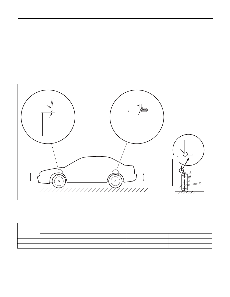
1. WHEEL ARCH HEIGHT

1) Park the vehicle on a level surface.
2) Empty the vehicle so that it is at “curb weight”.
(Empty the luggage compartment, load the spare
tire, jack and service tools, and fill up the fuel tank.)
3) Set the steering wheel in a straight-ahead posi-
tion, and stabilize the suspensions by moving the
vehicle in a straight line for 5 m (16 ft) or more.
4) Suspend a thread from the wheel arch (point “A”
in the figure below) and affix at a position directly
above the center of wheel.
5) Measure the distance between the point “A” and
the center of wheel.

(1)

Wheel arch height

(4)

Front wheel arch height

(7)

Point of measurement

(2)

Front fender

(5)

Rear wheel arch height

(8)

End of spindle

(3)

Rear quarter

(6)

Flange bend line


Wheel arch height specification mm (in) (Tolerance: 

+12 mm 

–24 mm

 (

+0.47 in

–0.94 in

))

Model

Sedan

Wagon

All models

Except for OUTBACK

OUTBACK

Front

381 (15.0)

381 (15.0)

439 (17.3)

Rear

365 (14.4)

375 (14.8)

438 (17.2)

FS-00125

A

A

A

(4)

(1)

(2)

(3)

(1)

(5)

(1)

(7)

(6)

(8)

FS-8

Wheel Alignment

FRONT SUSPENSION

2. CAMBER

• INSPECTION

1) Place the front wheel on the turning radius
gauge. Make sure the ground contact surfaces of
the front and rear wheels are at the same height.
2) Set the adapter into the center of wheel, and
then set the wheel alignment gauge.

3) Measure the camber angle in accordance with
the operation manual for wheel alignment gauge.

• FRONT CAMBER ADJUSTMENT

1) When adjusting the camber, adjust it to the fol-
lowing value.

2) Loosen the two self-locking nuts located at the
front lower section of the strut.

NOTE:
When the adjusting bolt needs to be loosened or
tightened, hold its head with a wrench and turn the
self-locking nut.
3) Turn the camber adjusting bolt so that the cam-
ber is set at specification.

NOTE:
Moving the adjusting bolt by one scale changes the
camber by approximately 0°15

c.

(1) Alignment gauge

(2) Turning radius gauge

(3) Adapter

Model

Camber (Difference between RH 

and LH 45

c or less)

Except for OUTBACK

–0°15

cr0°45c

OUTBACK

0°40

cr0°45c

FS-00213

(1)

(2)

(3)

Model

Camber (Difference between RH 

and LH 45

c or less)

Except for OUTBACK

–0°15

cr0°30c

OUTBACK

0°40

cr0°30c

(1) Strut

(2) Adjusting bolt

(3) Housing

(4) Outer

(5) Inner

(6) Camber is increased.

(7) Camber is decreased.

(1)

(4)

(6)

(7)

(2)

(3)

FS-00008

(5)

FS-9

Wheel Alignment

FRONT SUSPENSION

4) Tighten two new self-locking nuts.

Tightening torque:

155 N·m (15.8 kgf-m, 114.3 ft-lb)

To increase camber:

Rotate the left side counterclockwise.

Rotate the right side clockwise.

To decrease camber:

Rotate the left side clockwise.

Rotate the right side counterclockwise.

FS-00009

FS-00010

FS-00010

FS-00009

FS-10

Wheel Alignment

FRONT SUSPENSION

3. CASTER

INSPECTION

1) Place the front wheel on the turning radius
gauge. Make sure the ground contact surfaces of
the front and rear wheels are at the same height.
2) Set the adapter into the center of wheel, and
then set the wheel alignment gauge.

3) Measure the caster angle in accordance with the
operation manual for wheel alignment gauge.

4. STEERING ANGLE

• INSPECTION

1) Place the vehicle on turning radius gauge.
2) While depressing the brake pedal, turn the steer-
ing wheel fully to the left and right. With the steering
wheel held at each fully turned position, measure
both the inner and outer wheel steering angles.

• ADJUSTMENT

1) Turn the tie-rod to adjust the steering angle of
both inner and outer wheels.
2) Check the toe-in.

NOTE:
Correct the boot if it is twisted.

5. FRONT WHEEL TOE-IN

• INSPECTION

Toe-in:

0

r

3 mm (0

r

0.12 in)

1) Set the toe-in gauge in the position at wheel axis
center height behind the right and left front tires.
2) Place a mark at the center of both left and right
tires, and measure distance “A” between the
marks.
3) Move the vehicle forward to rotate the tires 180°.

NOTE:
Be sure to rotate the tires in the forward direction.
4) Measure the distance “B” between the left and
right marks. Find toe-in using the following equa-
tion:

A – B = Toe-in

(1) Alignment gauge

(2) Turning radius gauge

(3) Adapter

Model

Caster (Reference)

Sedan

5°55

c

Wagon

5°40

c

OUTBACK

4°55

c

Model

Inner wheel

Outer wheel

Other than below

37.6°

r1.5°

33.0°

r1.5°

2.5 GT spec.B, 
3.0 R-LTD

33.8°

r1.5°

30.2°

r1.5°

FS-00213

(1)

(2)

(3)

(1) Lock nut

FS-00014

(1)

FS-00015

A

B


Content   ..  838  839  840  841   ..