Subaru Legacy IV (2008 year). Manual - part 841


  Index      Subaru     Subaru Legacy IV - service repair manual 2008 year


Search            


Content   ..  839  840  841  842   ..


Subaru Legacy IV (2008 year). Manual - part 841


FS-11

Wheel Alignment

FRONT SUSPENSION

• ADJUSTMENT

When adjusting the toe-in, adjust it to the following
value.

Toe-in:

0

r

2 mm (0

r

0.08 in)

1) Check that the left and right wheel steering an-
gles are within specification.
2) Loosen the left and right side steering tie-rod
lock nuts.
3) Turn the left and right tie-rods by equal amounts
until the toe-in is at the specification.
Both the left and right tie-rods are right-hand
threaded. To increase toe-in, turn both tie-rods
clockwise by equal amount (viewing from the inside
of vehicle).

4) Tighten the tie-rod lock nut.

Tightening torque:

85 N·m (8.7 kgf-m, 62.7 ft-lb)

NOTE:
Check and correct the tie-rod boot if twisted.

6. REAR WHEEL TOE-IN

• INSPECTION

Toe-in:

OUTBACK model

–3 — 0 mm (–0.12 — 0 in)

Except for OUTBACK model

0

r

3 mm (0

r

0.12 in)

Refer to FRONT WHEEL TOE-IN for rear toe-in in-
spection procedures.
<Ref. to FS-10, FRONT WHEEL TOE-IN, INSPEC-
TION, Wheel Alignment.>

• ADJUSTMENT

When adjusting, adjust it to the following value.

Toe-in:

OUTBACK model

–3 — 0 mm (–0.12 — 0 in)

Except for OUTBACK model

0

r

2 mm (0

r

0.08 in)

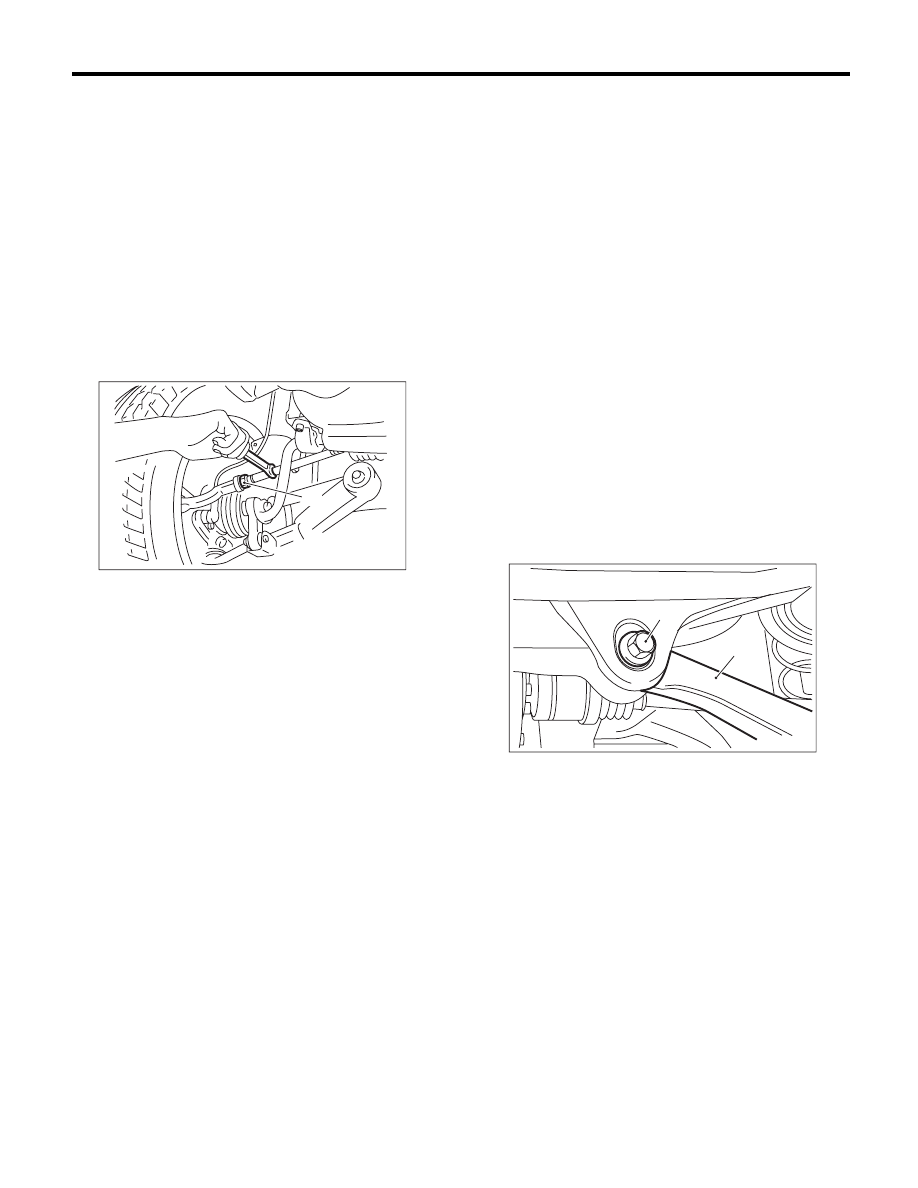
1) Loosen the self-locking nut on the inner side of
rear link.

NOTE:
When loosening or tightening the adjusting bolt,
hold the bolt head and turn the self-locking nut.

(1) Lock nut

FS-00014

(1)

(1) Adjusting bolt

(2) Rear link

FS-00103

(1)

(2)

FS-12

Wheel Alignment

FRONT SUSPENSION

2) Turn the adjusting bolt until toe-in is within the
specification.

NOTE:
When the left and right wheels are adjusted for toe-in
at the same time, the movement of one scale gradu-
ation changes toe-in by approx. 0.6 mm (0.02 in).

3) Attach and tighten a new self-locking nut.

Tightening torque:

120 N·m (12.2 kgf-m, 88.5 ft-lb)

To increase toe-in:

Rotate the left side clockwise.

Rotate the right side counterclockwise.

To decrease toe-in:

Rotate the left side counterclockwise.

Rotate the right side clockwise.

FS-00018

FS-00019

FS-00019

FS-00018

FS-13

Wheel Alignment

FRONT SUSPENSION

7. THRUST ANGLE

• INSPECTION

1) Park the vehicle on a level surface.
2) Move the vehicle 3 to 4 meters (10 to 13 feet)
straight forward.
3) Draw the center of loci for both the front and rear
axles.
4) Measure distance “L” between the center lines of
the axle loci.

Thrust angle

r

30

c

Less than 30

c

 when “L” is 23 mm (0.9 in) or less.

• ADJUSTMENT

When adjusting, adjust it to the following value.

Thrust angle

r

20

c

Less than 20

c

 when “L” is 15 mm (0.6 in) or less.

1) Make thrust angle adjustments by turning the
toe-in adjusting bolts of the rear suspension equally
in the same direction.
2) When one rear wheel is adjusted in a toe-in di-
rection, adjust the other rear wheel equally in toe-
out direction, in order to make the thrust angle ad-
justment.
3) When the left and right adjusting bolts are turned
by one graduation, the thrust angle will change ap-
prox. 17

c (“L” is approx. 13 mm (0.51 in)).

NOTE:
Thrust angle is a mean value of left and right wheel
toe angles in relation to the vehicle body center
line. Vehicle is driven straight in the thrust angle di-
rection while slanting in the oblique direction de-
pending on the degree of the mean thrust angle.

Thrust angle: r = (

D

 – 

E

)/2

D: Rear RH wheel toe-in angle
E: Rear LH wheel toe-in angle
Substitute only the positive toe-in values from each
wheel into 

D and E in the equation.

(1) Center line of loci (front axle)

(2) Center line of loci (rear axle)

(1)

(2)

L

FS-00022

(1) Front

(2) Thrust angle

(3) Body center line

(1) Front

(2) Body center line

FS-00024

(2)

(3)

(1)

FS-00976

(1)

(2)

FS-14

Front Crossmember Support Plate

FRONT SUSPENSION

3. Front Crossmember Support 

Plate

A: REMOVAL

1) Lift up the vehicle
2) Remove the front under cover. <Ref. to EI-26,
REMOVAL, Front Under Cover.>
3) Remove the bolt and remove front crossmember
support plate.
• Large type

• Small type

B: INSTALLATION

Install in the reverse order of removal.

NOTE:
Tighten the small type crossmember support plate
together with stabilizer bracket.
After installing the stabilizer bracket to the cross-
member, tighten the crossmember support plate to-
gether.

Tightening torque:

Crossmember support plate:

60 N·m (6.1 kgf-m, 44.3 ft-lb)

Crossmember support plate (Tightened to-
gether with the stabilizer bracket):

25 N·m (2.5 kgf-m, 18.1 ft-lb)

Jack-up plate:

60 N·m (6.1 kgf-m, 44.3 ft-lb)

(1) Crossmember support plate

(2) Jack-up plate

FS-00104

FS-00105

(2)

(1)

(1)


Content   ..  839  840  841  842   ..