Subaru Legacy IV (2008 year). Manual - part 843
FS-19
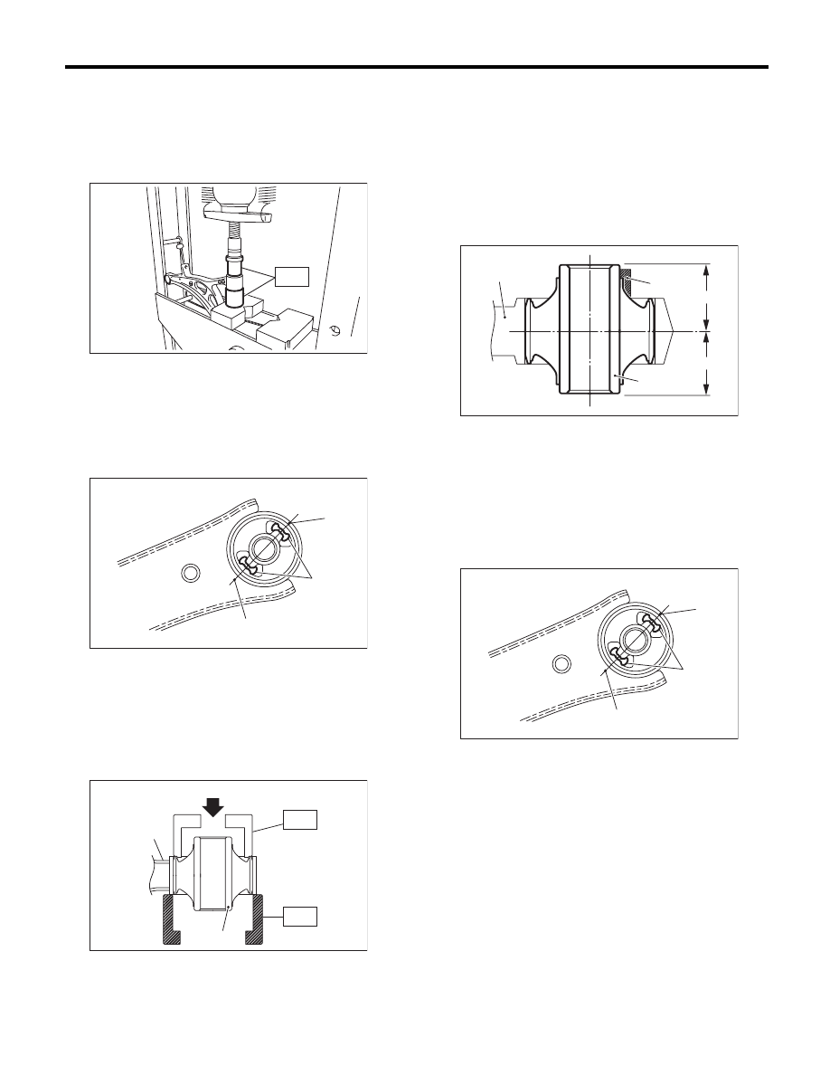
Front Arm
FRONT SUSPENSION
C: DISASSEMBLY
1. FRONT BUSHING
Using the ST and a press, remove the front bushing.
ST
927680000
INSTALLER & REMOVER
SET
2. REAR BUSHING
1) Put an alignment mark on the front arm based on
the center of rear bushing recess portion.
CAUTION:
Always put an alignment mark for aligning the
position on bushing installation.
2) Using the ST and a press, remove the rear bush-
ing.
ST1
20299AG000
REMOVER
ST2
20299AG010
BASE
D: ASSEMBLY
1. FRONT BUSHING
Assemble in the reverse order of disassembly.
2. REAR BUSHING
1) Install the rear bushing with its longer inner cyl-
inder facing upward and the shorter facing down-
ward and protruding part rearward as shown in the
figure.
2) Align the center of rear bushing recess portion
with the aligning mark on the front arm.
(1) Put an alignment mark.
(2) Recess section
(1) Press
(2) Front arm
(3) Rear bushing
ST
FS-00110
FS-00136
(2)
(1)
(1)
(1)
(2)
(3)
ST2
ST1
FS-00126
(1) Front arm
(2) Bushing inner cylinder
(3) Longer
(4) Shorter
(5) Protrusion portion
(1) Alignment mark
(2) Recess section
FS-00113
(2)
(1)
(3)
(4)
(5)
FS-00136
(2)
(1)
(1)