Subaru Legacy IV (2008 year). Manual - part 661
CS-51
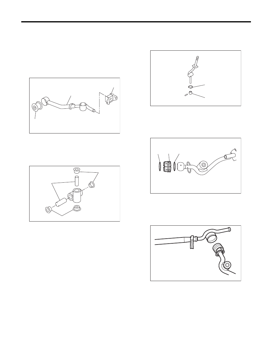
MT Gear Shift Lever
CONTROL SYSTEMS
2. 6MT MODEL
NOTE:
• Clean all the parts before assembly.
• Apply NIGTIGHT LYW No. 2 grease or the equiv-
alent to each part. <Ref. to CS-6, 6MT GEAR
SHIFT LEVER, COMPONENT, General Descrip-
tion.>
1) Mount the bushing and cushion rubber to the
stay.
2) Install the bushing and spacer to boss.
3) Install the snap ring to gear shift lever and install
the bushing.
NOTE:
Apply grease to the bushing.
4) Apply grease to the bushing and O-ring, and
then install to gear shift lever.
5) Apply sufficient grease to the boss, and then in-
stall the gear shift lever to the stay.
(A) Bushing
(B) Stay
(C) Cushion rubber
(A) Bushing
(B) Spacer
CS-00239
(B)
(C)
(A)
CS-00238
(B)
(A)
(A)
(A) Bushing
(B) Snap ring
(A) O-ring
(B) Bushing
CS-00237
(A)
(B)
CS-00236
(A)
(B)
(A)
CS-00235