Subaru Legacy IV (2008 year). Manual - part 659
CS-43
MT Gear Shift Lever
CONTROL SYSTEMS
8) Install the rear exhaust pipe and muffler.
• SOHC model
<Ref. to EX(H4SO)-8, INSTALLATION, Rear Ex-
haust Pipe.> <Ref. to EX(H4SO)-10, INSTALLA-
TION, Muffler.>
• DOHC turbo model
<Ref. to EX(H4DOTC)-13, INSTALLATION, Rear
Exhaust Pipe.> <Ref. to EX(H4DOTC)-14, IN-
STALLATION, Muffler.>
9) Install the plate assembly to the vehicle body.
Tightening torque:
18 N·m (1.8 kgf-m, 13.3 ft-lb)
(1) Set the plate assembly to the vehicle.
(2) Temporarily tighten the bolt (A).
(3) Tighten the bolt (B).
(4) Tighten the bolt (A).
(5) Tighten the bolts (C) and (D).
10) Install the harness clamp to the plate.
11) Install the boot and insulator assembly, and se-
cure with a clamp.
12) Install the front cover assembly.
13) Install the console box. <Ref. to EI-54, INSTAL-
LATION, Console Box.>
14) Install the shift knob.
15) Check that the gear can be shifted accurately
into each gear ranges.
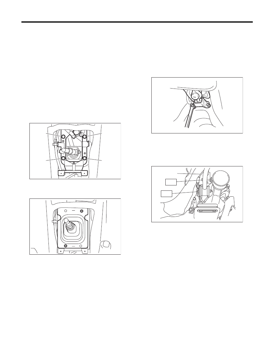
2. 6MT MODEL
1) Insert the gear shift lever from the room side.
NOTE:
Insert the rod and the stay, and position the lever
on top of the transmission mount.
2) Mount the cushion rubber on the vehicle body.
Tightening torque:
18 N·m (1.8 kgf-m, 13.3 ft-lb)
3) Move the transmission to the right side of the ve-
hicle, and attach the joint COMPL and stay.
Tightening torque:
T1: 12 N·m (1.2 kgf-m, 8.9 ft-lb)
T2: 32 N·m (3.3 kgf-m, 23.6 ft-lb)
4) Install the crossmember. <Ref. to 6MT-30, IN-
STALLATION, Transmission Mounting System.>
CS-00314
(B)
(A)
(C)
(D)
CS-00312
(A) Reverse check cable
CS-00222
CS-00223
(A)
T1
T2