Subaru Legacy IV (2008 year). Manual - part 658


  Index      Subaru     Subaru Legacy IV - service repair manual 2008 year


Search            


Content   ..  656  657  658  659   ..


Subaru Legacy IV (2008 year). Manual - part 658


CS-39

MT Gear Shift Lever

CONTROL SYSTEMS

8. MT Gear Shift Lever
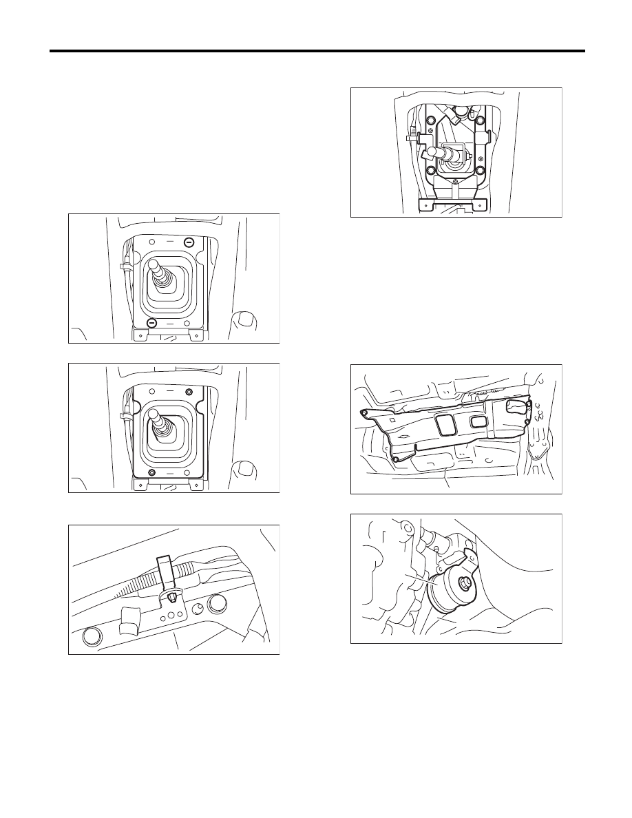
A: REMOVAL

1. 5MT MODEL

1) Set the vehicle on a lift.
2) Disconnect the ground cable from the battery.
3) Remove the gear shift knob.
4) Remove the console box. <Ref. to EI-54, RE-
MOVAL, Console Box.>
5) Remove the front cover assembly.
6) Remove the clamp.

7) Remove the bushing and insulator assembly.

8) Remove the harness clamp from the plate as-
sembly.

9) Remove the plate assembly from the vehicle
body.

10) Lift up the vehicle.
11) Remove the rear exhaust pipe and muffler.
• SOHC model
<Ref. to EX(H4SO)-8, REMOVAL, Rear Exhaust
Pipe.> <Ref. to EX(H4SO)-10, REMOVAL, Muf-
fler.>
• DOHC turbo model
<Ref. to EX(H4DOTC)-12, REMOVAL, Rear Ex-
haust Pipe.> <Ref. to EX(H4DOTC)-14, REMOV-
AL, Muffler.>
12) Remove the heat shield cover.

13) Remove the stay from transmission bracket.

CS-00311

CS-00312

CS-00313

(A) Stay

(B) Transmission bracket

CS-00563

AT-01331

CS-00050

(A)

(B)

CS-40

MT Gear Shift Lever

CONTROL SYSTEMS

14) Remove the rod from joint.

15) Remove the cushion rubber from the vehicle
body.

16) Extract the spring pin and remove the joint.

17) Lower the vehicle.

18) Remove the gear shift lever.

2. 6MT MODEL

1) Set the vehicle on a lift.
2) Disconnect the ground cable from the battery.
3) Remove the gear shift knob.
4) Remove the console box front. <Ref. to EI-54,
REMOVAL, Console Box.>
5) Remove the front cover assembly.
6) Remove the clamp.

7) Remove the bushing and insulator assembly.

8) Remove the harness clamp from the plate as-
sembly.

(A) Stay

(B) Rod

(A) Stay

(B) Cushion rubber

(A) Joint

(B) Spring pin

CS-00051

(A)

(B)

CS-00052

(A)

(B)

CS-00053

(A)

(B)

CS-00315

CS-00311

CS-00312

CS-00581

CS-41

MT Gear Shift Lever

CONTROL SYSTEMS

9) Remove the plate assembly from the vehicle
body.

10) Lift up the vehicle.
11) Remove the under cover.
12) Remove the rear exhaust pipe and muffler.
<Ref. to EX(H4DOTC)-12, REMOVAL, Rear Ex-
haust Pipe.> <Ref. to EX(H4DOTC)-14, REMOV-
AL, Muffler.>
13) Remove the heat shield cover.

14) Remove the crossmember. <Ref. to 6MT-30,
REMOVAL, Transmission Mounting System.>
15) Remove the snap pin and washer, and remove
the reverse check cable from the reverse check le-
ver.

16) Move the transmission to the right side, and re-
move the joint COMPL, stay bolts and reverse
check cable.

NOTE:
If the transmission is not moved aside, the joint
COMPL and stay bolts may contact the body and
cause damage.

17) Remove the cushion rubber from the vehicle
body.

18) Lower the vehicle.
19) Remove the gear shift lever.

(A) Snap pin

(B) Washer

(C) Reverse check cable

CS-00584

AT-01331

CS-00220

(B)

(A)

(C)

(A) Joint COMPL bolt

(B) Stay bolt

(C) Reverse check cable

CS-00221

(C)

(A)

(B)

CS-00222

CS-42

MT Gear Shift Lever

CONTROL SYSTEMS

B: INSTALLATION

1. 5MT MODEL

1) Install the joint to the transmission and secure
with a spring pin.

2) Insert the gear shift lever from the room side.

NOTE:
Insert the rod and the stay, and then temporarily set
them onto the transmission mount.

3) Lift up the vehicle.
4) Mount the cushion rubber on the vehicle body.

Tightening torque:

18 N·m (1.8 kgf-m, 13.3 ft-lb)

5) Using new self-locking nuts, connect the rod to
the joint.

Tightening torque:

18 N·m (1.8 kgf-m, 13.3 ft-lb)

6) Using new self-locking nuts, connect the stay to
the transmission bracket.

Tightening torque:

18 N·m (1.8 kgf-m, 13.3 ft-lb)

7) Install the heat shield cover.

(A) Joint

(B) Spring pin

(A) Stay

(B) Cushion rubber

CS-00053

(A)

(B)

CS-00315

CS-00052

(A)

(B)

(A) Stay

(B) Rod

(A) Stay

(B) Transmission bracket

CS-00051

(A)

(B)

CS-00050

(A)

(B)

AT-01331


Content   ..  656  657  658  659   ..