Subaru Legacy IV (2008 year). Manual - part 656
CS-31
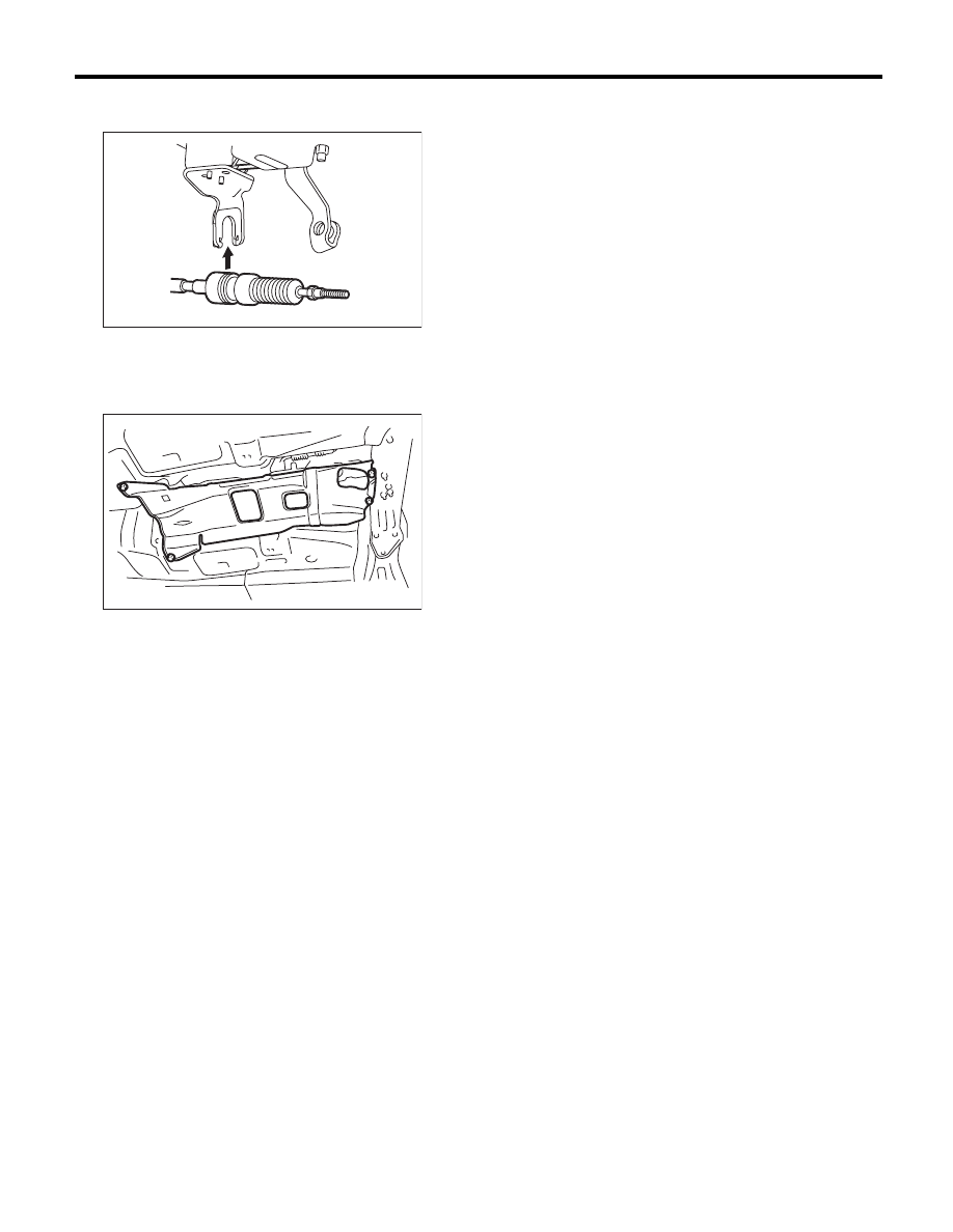
Select Cable
CONTROL SYSTEMS
8) Insert the tip of inner cable into connector hole of
select lever, and fix the cable to bracket.
9) Shift the select lever to the “N” range, and then
adjust the select cable position. <Ref. to CS-32,
ADJUSTMENT, Select Cable.>
10) Install the heat shield cover.
11) Install the front, center and rear exhaust pipes,
and the muffler. (Non-turbo model)
• SOHC model
<Ref. to EX(H4SO)-5, INSTALLATION, Front Ex-
haust Pipe.> <Ref. to EX(H4SO)-7, INSTALLA-
TION, Center Exhaust Pipe.> <Ref. to EX(H4SO)-
8, INSTALLATION, Rear Exhaust Pipe.> <Ref. to
EX(H4SO)-10, INSTALLATION, Muffler.>
• DOHC 3.0 L model
<Ref. to EX(H6DO)-5, INSTALLATION, Front Ex-
haust Pipe.> <Ref. to EX(H6DO)-8, INSTALLA-
TION, Rear Exhaust Pipe.> <Ref. to EX(H6DO)-9,
INSTALLATION, Muffler.>
12) Install the center, rear exhaust pipes and the
muffler. (Turbo model)
<Ref. to EX(H4DOTC)-9, INSTALLATION, Center
Exhaust Pipe.> <Ref. to EX(H4DOTC)-13, IN-
STALLATION, Rear Exhaust Pipe.> <Ref. to
EX(H4DOTC)-14, INSTALLATION, Muffler.>
C: INSPECTION
Check the removed cable and replace or adjust if
damaged, rusty or malfunctioning.
1) Check the cable for smooth operation.
2) Check the inner cable for damage and rust.
3) Check the outer cable for damage, bends and
cracks.
4) Check the boot for damage, cracks and deterio-
ration.
5) Move the select lever from “P” to “D” range.
Check the existence of feel to contact the detents in
each range. If the detents cannot be felt or the po-
sition pointer is improperly aligned, adjust the ca-
ble.
6) Check if the starter motor rotates when the se-
lect lever is set to “P” range.
7) Check the back-up light illumination when the
select lever is in “R” range.
8) Check the parking lock operation when the se-
lect lever is in “P” range.
CS-00330
AT-01331