Subaru Legacy IV (2008 year). Manual - part 654


  Index      Subaru     Subaru Legacy IV - service repair manual 2008 year


Search            


Content   ..  652  653  654  655   ..


Subaru Legacy IV (2008 year). Manual - part 654


CS-23

Select Lever

CONTROL SYSTEMS

3. Select Lever

A: REMOVAL

1) Set the vehicle on a lift.
2) Disconnect the ground cable from the battery.
3) Shift the select lever to “N” range.
4) Lift up the vehicle.
5) Remove the rear exhaust pipe and muffler.
• SOHC model
<Ref. to EX(H4SO)-8, REMOVAL, Rear Exhaust
Pipe.> <Ref. to EX(H4SO)-10, REMOVAL, Muf-
fler.>
• DOHC turbo model
<Ref. to EX(H4DOTC)-12, REMOVAL, Rear Ex-
haust Pipe.> <Ref. to EX(H4DOTC)-14, REMOV-
AL, Muffler.>
• DOHC 3.0 L model
<Ref. to EX(H6DO)-7, REMOVAL, Rear Exhaust
Pipe.> <Ref. to EX(H6DO)-9, REMOVAL, Muffler.>
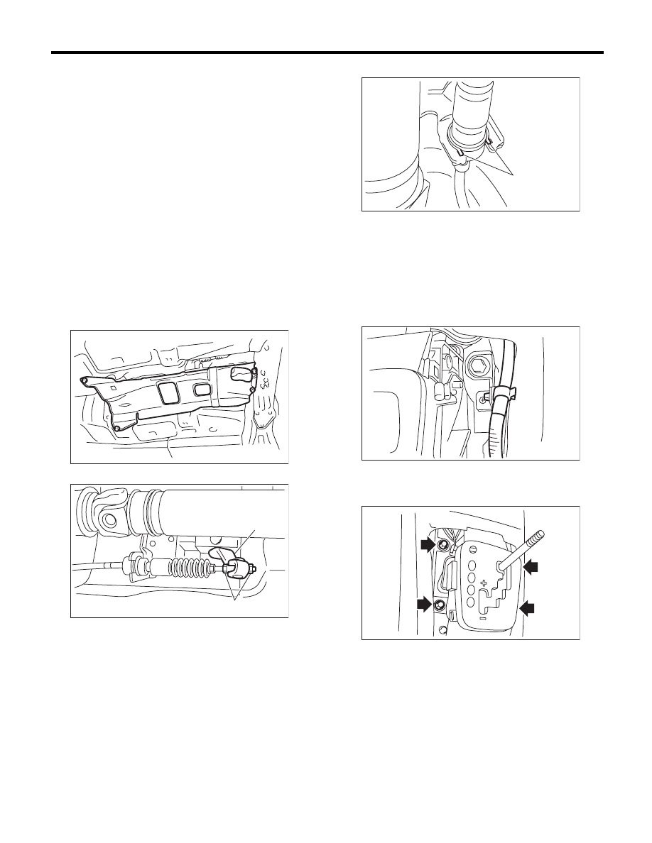
6) Remove the heat shield cover.

7) Remove the cable from the arm assembly.

8) Raise the claw of clamp to remove the cable.

9) Lower the vehicle.
10) Remove the console box. <Ref. to EI-54, RE-
MOVAL, Console Box.>
11) Remove the center console. <Ref. to EI-55,
REMOVAL, Center Console.>
12) Remove the harness clips from the bracket.

13) Disconnect the connectors, and then remove
the four bolts to take out the select lever assembly
from vehicle body.

(A) Adjusting nut

(B) Arm ASSY

AT-01331

(B)

CS-00278

(A)

(A) Claw

CS-00279

(A)

CS-00518

CS-00519

CS-24

Select Lever

CONTROL SYSTEMS

B: INSTALLATION

1) Set the select lever to vehicle body.
2) Tighten the four bolts to install the select lever to
vehicle body, and then connect the connector.

(1) Temporarily tighten the bolt A.
(2) Tighten the bolt B.
(3) Tighten the bolt A.
(4) Tighten the bolts C and D.

Tightening torque:

18 N·m (1.8 kgf-m, 13.3 ft-lb)

3) Install the harness clips to the bracket.

4) Install the center console. <Ref. to EI-56, IN-
STALLATION, Center Console.>
5) Install the console box. <Ref. to EI-54, INSTAL-
LATION, Console Box.>
6) Shift the select lever to “N” range.
7) Lift up the vehicle.
8) Shift the range select lever to the “N” range.
9) Secure the cable to the bracket. <Ref. to CS-30,
INSTALLATION, Select Cable.>
10) Adjust the select cable position. <Ref. to CS-
32, ADJUSTMENT, Select Cable.>
11) After the completion of adjustment, confirm that
the select lever operates properly at all range posi-
tions.
12) Install the heat shield cover.

13) Install the rear exhaust pipe and muffler.
• SOHC model
<Ref. to EX(H4SO)-8, INSTALLATION, Rear Ex-
haust Pipe.> <Ref. to EX(H4SO)-10, INSTALLA-
TION, Muffler.>
• DOHC turbo model
<Ref. to EX(H4DOTC)-13, INSTALLATION, Rear
Exhaust Pipe.> <Ref. to EX(H4DOTC)-14, IN-
STALLATION, Muffler.>
• DOHC 3.0 L model
<Ref. to EX(H6DO)-8, INSTALLATION, Rear Ex-
haust Pipe.> <Ref. to EX(H6DO)-9, INSTALLA-
TION, Muffler.>
14) Inspect the following items. When a malfunc-
tion is found in the inspection, adjust the select ca-
ble and inhibitor switch. <Ref. to CS-32,
ADJUSTMENT, Select Cable.> <Ref. to 4AT-46,
ADJUSTMENT, Inhibitor Switch.>

NOTE:
Inhibitor switch for 5AT model is not adjustable.

(1) Engine starts when the select lever is in “P”
and “N” range, but not in other ranges.
(2) Back-up light illuminates when the select le-
ver is in the “R” range, but not in other ranges.
(3) Select lever and indicator positions are
matched.

CS-00520

A

B

D

C

CS-00518

CS-25

Select Lever

CONTROL SYSTEMS

C: DISASSEMBLY

1) Shift the select lever to “N” range.
2) Remove the indicator bulb.

3) Remove the grip.
4) Remove the indicator assembly.

5) Remove the blind.

6) Shift the select lever to the “N” range, and then
remove the detent spring.

7) Remove the bolt, and separate the guide plate
upper from plate lower.

8) Remove the connector from the guide plate up-
per.

9) Remove the sheet, and remove the shift lock so-
lenoid assembly.

10) Remove the switch assembly.

CS-00521

CS-00522

CS-00523

CS-00538

(A) Guide plate upper

(B) Plate lower

CS-00524

(A)

(B)

CS-00525

CS-00526

CS-00527

CS-26

Select Lever

CONTROL SYSTEMS

11) Remove the check plate.

12) Raise the claw of connector.

13) Disconnect the terminals of the SPORT mode
switch and shift lock solenoid assembly from the
connector, using a flat tip screwdriver with a thin tip.

14) Remove the cable bracket.

15) Remove the gasket.

16) Remove the select lever assembly.

17) Remove the clamp, and remove the arm as-
sembly and bushing plate.

(A) “P” range switch

CS-00528

CS-00292

CS-00529

4

10

3
9 8 7

2 1
6 5

(A)

CS-00530

(A) Arm ASSY

(B) Bushing plate

(C) Bushing A

(D) Bushing B

CS-00531

CS-00532

CS-00686

(C)

(D)

(C)

(B)

(A)


Content   ..  652  653  654  655   ..