Subaru Legacy IV (2008 year). Manual - part 1140


  Index      Subaru     Subaru Legacy IV - service repair manual 2008 year


Search            


Content   ..  1138  1139  1140  1141   ..


Subaru Legacy IV (2008 year). Manual - part 1140


EI-59

Instrument Panel Assembly

EXTERIOR/INTERIOR TRIM

2. STEERING SUPPORT BEAM

1) Remove the instrument panel. <Ref. to EI-57,
INSTRUMENT PANEL (EXCLUDING STEERING
SUPPORT BEAM), REMOVAL, Instrument Panel
Assembly.>
2) Remove the steering shaft assembly. <Ref. to
PS-16, REMOVAL, Tilt Steering Column.>
3) Remove all harness clips, and remove the har-
ness from the steering support beam.

NOTE:
If necessary, make alignment marks for easy reas-
sembly.
4) Remove the bolts and remove the steering sup-
port beam.

5) Remove the steering support beam bracket.

3. INSTRUMENT PANEL ASSEMBLY 
(INCLUDING STEERING SUPPORT BEAM)

CAUTION:
Be careful not to damage the airbag system
harness when servicing the instrument panel.
Damage may cause the system to malfunction.
1) Remove the front pillar upper trim. <Ref. to EI-
62, REMOVAL, Upper Inner Trim.>
2) Remove the center console. <Ref. to EI-55, RE-
MOVAL, Center Console.>
3) Remove the instrument panel lower cover. <Ref.
to EI-51, REMOVAL, Instrument Panel Lower Cov-
er.>
4) Remove the glove box. <Ref. to EI-52, REMOV-
AL, Glove Box.>
5) Remove the steering shaft assembly. <Ref. to
PS-16, REMOVAL, Tilt Steering Column.>

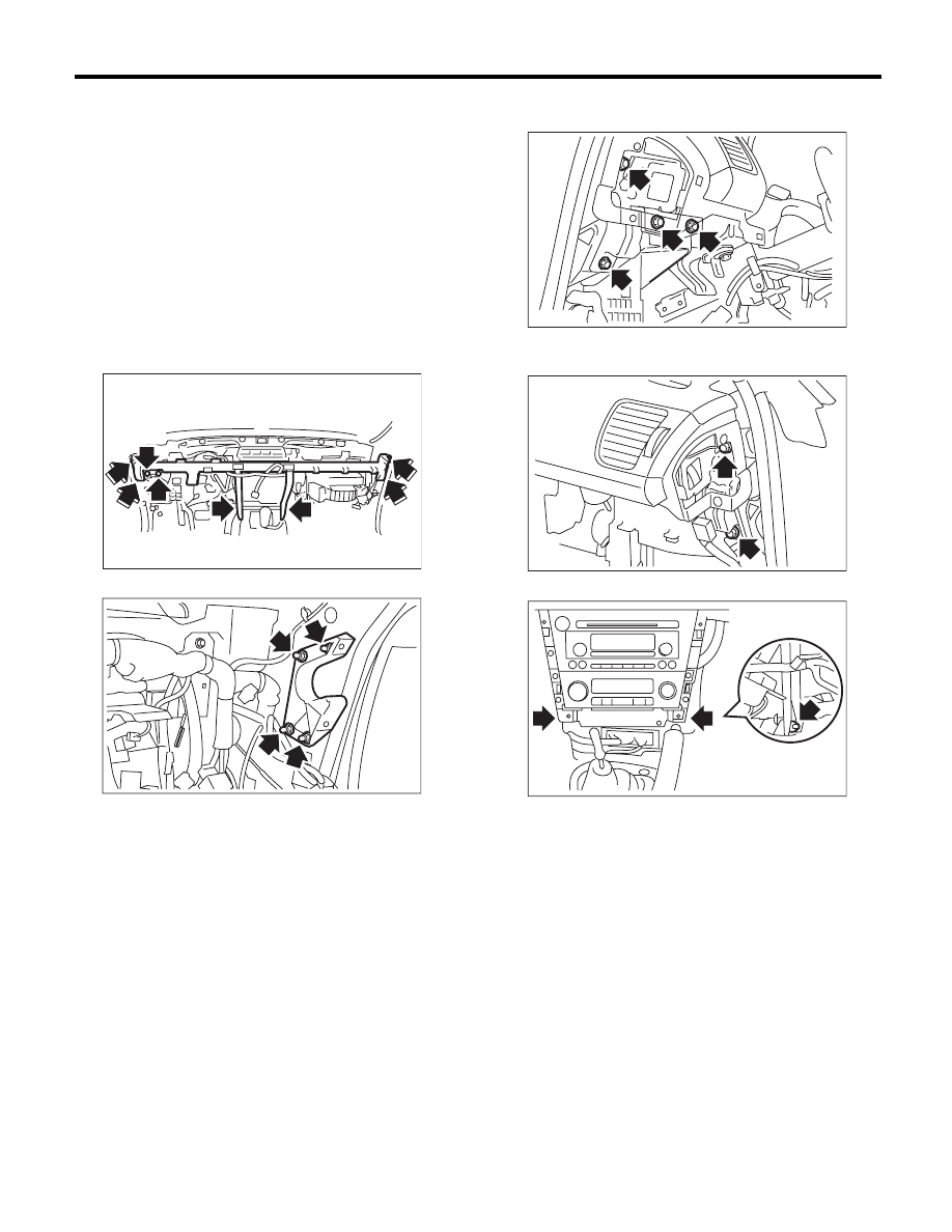
6) Remove the driver’s side instrument panel side
cover, and remove the bolts.

7) Remove the bolts at the side of the passenger’s
side instrument panel.

8) Loosen the bolts on the center console side.

9) Disconnect the connectors, and remove the in-
strument panel assembly.

NOTE:
If necessary, make alignment marks for easy reas-
sembly.

EI-00775

EI-00617

EI-00776

EI-00777

EI-00620

EI-60

Instrument Panel Assembly

EXTERIOR/INTERIOR TRIM

B: INSTALLATION

1. INSTRUMENT PANEL 
(EXCLUDING STEERING SUPPORT BEAM)

1) Insert the matching pins (three places) on the in-
strument panel tip into the grommet (A) and (B) on
the body panel side.

2) Check that the matching pins are inserted se-
curely, and then route the harness.
3) Tighten the instrument panel with screws, and
recheck the installation condition of instrument
panel and harness routing.
4) Install in the reverse order of removal.

NOTE:
How to install insulator and pad;
• Adhesive
Use polyurethane adhesive. When assembling the
instrument panel assembly, wait until the adhesive
has evaporated to prevent filling of the smell in the
compartment.
• Double-sided tape
Use commercial double-sided tape. (Use strong
double-sided adhesive tape.)
• Locations

Apply at a position spaced by 10 mm from the in-
strument panel front end, and 40 mm from the ends
on both sides.

2. STEERING SUPPORT BEAM

1) Temporarily tighten the steering support beam
with bolts, and then route the harness.
2) Make sure that there is no mutual interference in
each pedal, and then tighten each bolt.

Tightening torque:

25 N·m (2.55 kgf-m, 18.4 ft-lb)

3) Install in the reverse order of removal.

3. INSTRUMENT PANEL ASSEMBLY 
(INCLUDING STEERING SUPPORT BEAM)

1) Insert the matching pins (three places) on the in-
strument panel tip into the grommet (A) and (B) on
the body panel side.

2) Check that the matching pins are inserted se-
curely, and then route the harness.
3) Temporarily tighten the steering support beam
with bolts, and then route the harness.
4) Make sure that there is no mutual interference in
each pedal, and then tighten each bolt.

Tightening torque:

25 N·m (2.55 kgf-m, 18.4 ft-lb)

5) Install in the reverse order of removal.

(1) 10 mm

(2) 40 mm

EI-00621

(B)

(B)

(A)

EI-01087

(2)

(1)

(2)

EI-00621

(B)

(B)

(A)

EI-61

Lower Inner Trim

EXTERIOR/INTERIOR TRIM

23.Lower Inner Trim

A: REMOVAL

1) Remove the hook, and remove the inside scuff
plate.

2) Remove the door molding (A), and remove the
outside scuff plate.

3) Remove clip (A), and remove the front pillar low-
er trim.

4) Remove the rear seat cushion. <Ref. to SE-18,
REMOVAL, Rear Seat.>

5) Remove clip (A), and remove the inside scuff
plate.

6) Remove door molding (A) and door catcher cov-
er (B), then remove the outside scuff plate.

7) Remove the clips of the center pillar lower trim.

B: INSTALLATION

Install in the reverse order of removal.

(A) Hook

(B) Clip

EI-00778

: (A)

(A)

EI-00779

: (B)

(A)

EI-00780

(B) Hook

(C) Hook with plate clip

(D) Clip

(A)

EI-00781

: (B)

EI-00782

(A)

:(C)

:(D)

(B)

EI-01027

EI-62

Upper Inner Trim

EXTERIOR/INTERIOR TRIM

24.Upper Inner Trim

A: REMOVAL

1) From the top side of the trim, remove the metal
clip using a flat tip screwdriver.

CAUTION:
When the metal clip comes off or becomes
damaged, replace both trim and metal clips
with new parts.

2) Remove the front pillar upper trim.

3) Remove the front inside scuff plate, rear inside
scuff plate and center pillar lower trim. <Ref. to EI-
61, REMOVAL, Lower Inner Trim.>
4) Remove the cap on the upper side of the pillar
trim, and remove the bolt inside.

5) Remove the center pillar upper trim.

6) Remove the seat belt lower anchor bolt at the
center pillar lower port. (Driver’s seat)
7) Refer to the removal procedure of “Front Seat
Belt” for the passenger’s seat. <Ref. to SB-18,
OUTER SEAT BELT ASSEMBLY, REMOVAL,
Front Seat Belt.>

B: INSTALLATION

Install in the reverse order of removal.

Tightening torque:

7.5 N·m (0.76 kgf-m, 5.5 ft-lb)

EI-00785

EI-00786

EI-00562

EI-01028


Content   ..  1138  1139  1140  1141   ..