Subaru Legacy IV (2008 year). Manual - part 72
ME(H4SO)-84
Cylinder Block
MECHANICAL
6) Boring and honing
(1) If any of the measured value of taper, out-of-
roundness or cylinder-to-piston clearance is out
of standard or if there is any damage on the cyl-
inder wall, rebore it to replace with an oversize
piston.
CAUTION:
When any of the cylinders needs reboring, oth-
er cylinders must be bored at the same time,
and replaced with oversize pistons.
(2) If the cylinder inner diameter exceeds the
limit after boring and honing, replace the cylin-
der block.
NOTE:
Immediately after reboring, the cylinder diameter
may differ from its real diameter due to temperature
rise. Thus, when measuring the cylinder diameter,
wait until it has cooled to room temperature.
Cylinder inner diameter boring limit (diameter):
To 100.005 mm (3.9372 in)
3. PISTON AND PISTON PIN
1) Check the piston and piston pin for breaks,
cracks or wear. Replace if faulty.
2) Check the piston ring groove for wear and dam-
age. Replace if faulty.
3) Make sure that the piston pin can be inserted
into the piston pin hole with a thumb at 20°C (68°F).
Replace if faulty.
Clearance between piston hole and piston pin:
Standard
0.004 — 0.008 mm (0.0002 — 0.0003 in)
4) Check the snap ring installation groove (A) on
the piston for burr. If necessary, remove burr from
the groove so that the piston pin can lightly move.
5) Check the piston pin snap ring for distortion,
cracks and wear.
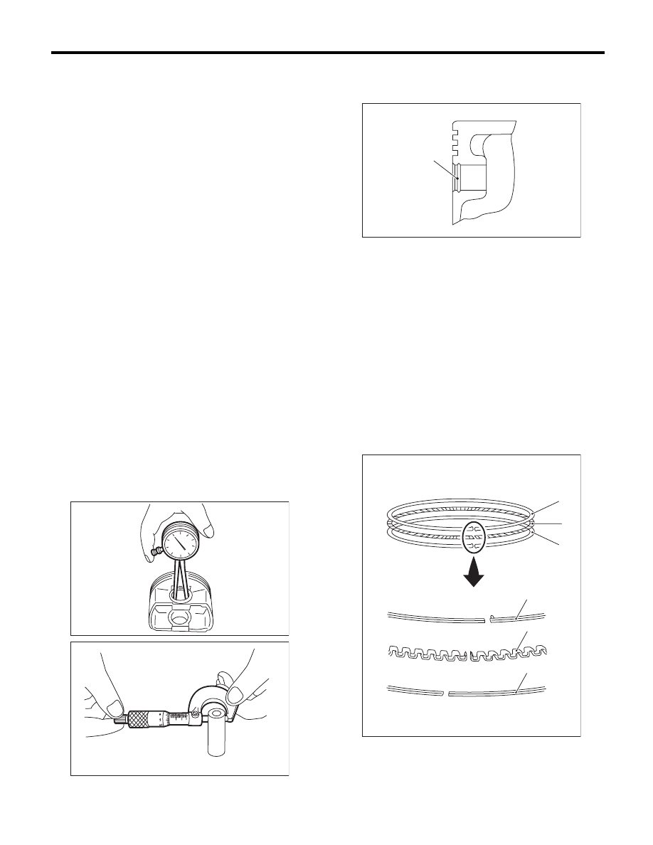
4. PISTON RING
1) If the piston ring is broken, damaged or worn, or
if its tension is insufficient, or when the piston is re-
placed, replace the piston ring with a new part of
the same size as piston.
NOTE:
• The top ring and second ring have the mark to
determine the direction for installing. When install-
ing the ring to piston, face these marks to the top
side.
• Oil ring consists of the upper rail, expander and
lower rail. When installing the oil ring on piston, be
careful of each rails direction.
ME-00173
ME-00174
(A) Upper rail
(B) Expander
(C) Lower rail
ME-00175
(A)
ME-02480
(A)
(B)
(C)
(A)
(B)
(C)