Subaru Legacy IV (2008 year). Manual - part 70
ME(H4SO)-76
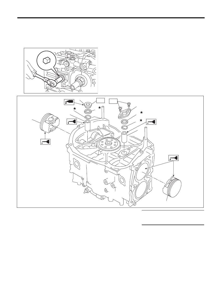
Cylinder Block
MECHANICAL
(6) Install the service hole plug and gasket.
NOTE:
Use a new gasket.
Tightening torque:
70 N·m (7.1 kgf-m, 51.6 ft-lb)
ME-00140
(1)
Piston
(5)
Service hole plug
Tightening torque:N·m (kgf-m, ft-lb)
(2)
Piston pin
(6)
Service hole cover
T1: 6.4 (0.7, 4.7)
(3)
Snap ring
(7)
O-ring
T2: 70 (7.1, 51.6)
(4)
Gasket
(2)
(3)
(1)
(2)
(6)
(3)
(7)
(4)
(5)
ME-02440
T2
T1
(1)