Subaru Legacy IV (2008 year). Manual - part 71
ME(H4SO)-80
Cylinder Block
MECHANICAL
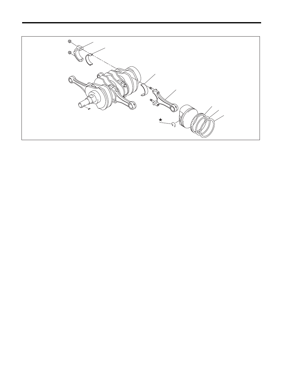
C: DISASSEMBLY
1) Remove the connecting rod cap.
2) Remove the connecting rod bearing.
NOTE:
Keep the removed connecting rods, connecting rod
caps and bearings in order so that they are kept in
their original combinations/groups, and not mixed
together.
3) Remove the piston rings using piston ring ex-
pander.
4) Remove the oil ring by hand.
NOTE:
Arrange the removed piston rings in proper order,
to prevent confusion.
5) Remove the snap ring.
(1)
Connecting rod cap
(4)
Second ring
(6)
Snap ring
(2)
Connecting rod bearing
(5)
Oil ring
(7)
Connecting rod
(3)
Top
ring
ME-03562
(2)
(2)
(6)
(5)
(4)
(3)
(1)
(7)