SsangYong Korando II (1996-2006 year). Manual - part 274


  Index      SsangYong     SsangYong Korando II - service repair manual 1996-2006 year


Search            


Content   ..  272  273  274  275   ..


SsangYong Korando II (1996-2006 year). Manual - part 274


PARKING BRAKE  4G-7

SSANGYONG MY2002

SPECIFICATIONS

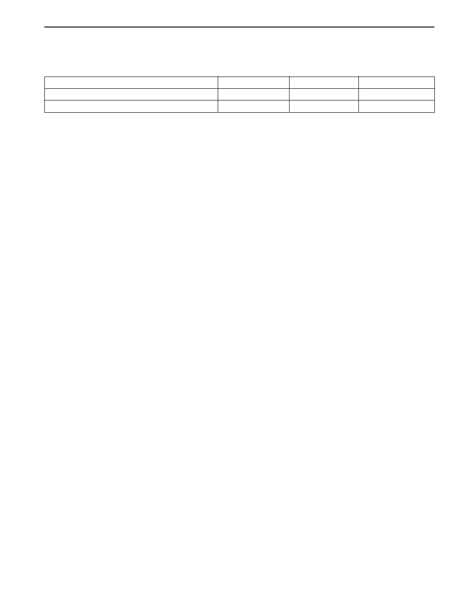
FASTENER TIGHTENING SPECIFICATIONS

13

-

Parking Brake Lever Mounting Bolts

Rear Parking Brake Cable Securing Bolts

N • m

Application

Lb-In

Lb-Ft

18

9

-

80

SECTION 5A

AUTOMATIC TRANSMISSION

CAUTION: Disconnect the negative battery cable before removing or installing any electrical unit or when a
tool or equipment could easily come in contact with exposed electrical terminals. Disconnecting this cable
will help prevent personal injury and damage to the vehicle. The ignition must also be in LOCK unless
otherwise noted.

TABLE OF CONTENTS

Description and Operation . . . . . . . . . . . . . . . . .  5A-2

BTRA M74 4WD Automatic Transmission . . . . . .  5A-2

Operators Interfaces . . . . . . . . . . . . . . . . . . . . .  5A-2

Control Systems . . . . . . . . . . . . . . . . . . . . . . . .  5A-3

Electronic Control System . . . . . . . . . . . . . . . . .  5A-3

Hydraulic Control System . . . . . . . . . . . . . . . . . .  5A-9

Hydraulic Control Circuit . . . . . . . . . . . . . . . . . .  5A-10

Power Train System . . . . . . . . . . . . . . . . . . . . .  5A-14

Power Flows . . . . . . . . . . . . . . . . . . . . . . . . . .  5A-18

Park and Neutral . . . . . . . . . . . . . . . . . . . . . . .  5A-20

Reverse . . . . . . . . . . . . . . . . . . . . . . . . . . . . . .  5A-22

Manual 1 . . . . . . . . . . . . . . . . . . . . . . . . . . . . .  5A-24

Drive 1 . . . . . . . . . . . . . . . . . . . . . . . . . . . . . .  5A-26

Drive 2 and Manual 2 . . . . . . . . . . . . . . . . . . . .  5A-28

Drive 3 and Manual 3 . . . . . . . . . . . . . . . . . . . .  5A-30

Drive 3 Lock Up and Manual 3 Lock Up . . . . . .  5A-32

Drive 4  (Overdrive) . . . . . . . . . . . . . . . . . . . . .  5A-34

Drive 4 Lock Up . . . . . . . . . . . . . . . . . . . . . . . .  5A-36

Diagnostic Information and Procedures . . . . .  5A-38

Diagnosis . . . . . . . . . . . . . . . . . . . . . . . . . . . . .  5A-38

Basic Knowledge Required . . . . . . . . . . . . . . .  5A-38

Functional Check Procedure . . . . . . . . . . . . . . .  5A-38

Transmission Fluid Level Service Procedure . . .  5A-38

Fluid Leak Diagnosis and Repair . . . . . . . . . . .  5A-39

Electrical / Garage Shift Test . . . . . . . . . . . . . .  5A-40

Road Test Procedure . . . . . . . . . . . . . . . . . . . .  5A-40

Electronic Adjustments . . . . . . . . . . . . . . . . . .  5A-40

Symptom Diagnosis . . . . . . . . . . . . . . . . . . . . .  5A-41

Drive Faults . . . . . . . . . . . . . . . . . . . . . . . . . . .  5A-41

Faulty Shift Pattern . . . . . . . . . . . . . . . . . . . . . .  5A-42

Shift Quality Faults . . . . . . . . . . . . . . . . . . . . . .  5A-44

After Teardown Faults . . . . . . . . . . . . . . . . . . .  5A-46

Trouble Code Diagnosis - Gasoline Vehicle . .  5A-48

TCM Diagnostic System Overview . . . . . . . . . .  5A-48

Clearing Trouble Codes . . . . . . . . . . . . . . . . . .  5A-48

Diagnostic Trouble Codes . . . . . . . . . . . . . . . .  5A-48

Trouble Code Diagnosis - Diesel Vehicle . . . . .  5A-50

TCM Diagnostic System Overview . . . . . . . . . .  5A-50

Clearing Trouble Codes . . . . . . . . . . . . . . . . . .  5A-50

Diagnostic Trouble Codes . . . . . . . . . . . . . . . .  5A-50

Repair Instructions . . . . . . . . . . . . . . . . . . . . . . 5A-157

On-Vehicle Service . . . . . . . . . . . . . . . . . . . . . . . 5A-157

Transmission . . . . . . . . . . . . . . . . . . . . . . . . . . 5A-157

Unit Repair . . . . . . . . . . . . . . . . . . . . . . . . . . . . 5A-160

Rebuild Warnings . . . . . . . . . . . . . . . . . . . . . . 5A-160

Disassembly Procedure . . . . . . . . . . . . . . . . . . 5A-161

Assembly Procedure . . . . . . . . . . . . . . . . . . . . 5A-171

Front and Rear Band Adjustment . . . . . . . . . . . 5A-199

Gear Shift Control Lever . . . . . . . . . . . . . . . . . . 5A-202

Kickdown Switch . . . . . . . . . . . . . . . . . . . . . . . 5A-202

Specifications . . . . . . . . . . . . . . . . . . . . . . . . . . 5A-203

General Specification . . . . . . . . . . . . . . . . . . . . 5A-203

Fastener Tightening Specifications . . . . . . . . . . 5A-205

Schematic and Routing Diagrams . . . . . . . . . . 5A-206

TCM Wiring Diagrams (Gasoline Engine) . . . . .  5A-206

TCM Wiring Diagrams (Diesel Engine) . . . . . . . 5A-208

Connector End View . . . . . . . . . . . . . . . . . . . . . 5A-210

Special Tools and Equipment . . . . . . . . . . . . .  5A-211

Special Tools Table . . . . . . . . . . . . . . . . . . . . . 5A-211

5A-2  AUTOMATIC TRANSMISSION

SSANGYONG  MY2002

OPERATORS INTERFACES

There are three operator interfaces as the following;

Gear Shift Control Lever

Driving Mode Selector

Indicator Light

Gear Shift Control lever

The transmission uses a conventional shift control lever.
The gear shift control lever can be moved from one
position to another within the staggered configuration
of the shift control lever gate to positively indicate the
gear selection.

DESCRIPTION AND OPERATION

BTRA M74 4WD AUTOMATIC
TRANSMISSION

The BTR Automotive Model 74 Four Speed Automatic
Transmission is an electronically controlled overdrive
four speed unit with a lock-up torque converter. The
lock-up torque converter results in lower engine speeds
at cruise and eliminates unnecessary slippage. These
features benefit the customer through improved fuel
economy and noise reduction.

Of primary significance is the Transmission Control Mo-
dule (TCM) which is a microprocessor based control
system.

The TCM utilizes throttle position, rate of throttle open-
ing, engine speed, vehicle speed, transmission fluid
temperature, gear selector position and mode selector
inputs, and in some applications a Kickdown Switch
to control all shift feel and shift schedule aspects.

The TCM drives a single proportional solenoid multi-
plexed to three regulator valves to control all shift feel
aspects. The output pressure of this solenoid is con-
trolled as a function of transmission fluid temperature
to maintain consistent shift feel throughout the
operating range.

Shift scheduling is highly flexible, and several indepen-
dent schedules are programmed depending on the ve-
hicle.

Typically the NORMAL schedule is used to maximize
fuel economy and driveability, and a POWER schedule
is used to maximize performance. WINTER schedule
is used to facilitate starting in second gear.

Configuration

Max.

Power

 (kW)

320

160

260 mm Torque

Converter-Wide

Ratio Gear Set

Splined Output for Transfer

Case

P - Park position prevents the vehicle from rolling
e i t h e r   f o r w a r d   o r   b a c k w a r d   b y   l o c k i n g   t h e
transmission output shaft. The inhibitor switch
allows the engine to be started. For safety reasons,
the parking should be used in addition to the park
position. Do not select the Park position until the
vehicle comes to a complete stop because it
mechanically locks the output shaft.

R - Reverse allows the vehicle to be operated in a
rearward direction. The inhibitor switch enables re-
verse lamp operation.

KAA5A010

AUTOMATIC TRANSMISSION  5A-3

SSANGYONG  MY2002

N - Neutral allows the engine to be started and oper-
ated while driving the vehicle. The inhibitor switch
allows the engine to be started. There is no power
transferred through the transmission in Neutral. But
the final drive is not locked by the parking pawl, so
thewheels are free to rotate.

D - Overdrive range is used for all normal driving
conditions. 4th gear (overdrive gear) reduces the
fuel consumption and the engine noise. Engine
braking is applied with reduced throttle.

First to second (1 

 2), first to third (1 

 3), second

to third (2 

 3), second to fourth (2 

 4), third to

fourth (3 

 4), fourth to third (4 

 3), fourth to

second (4 

 2), third to second (3 

 2), third to

first (3 

 1) and second to first (2 

 1) shifts are

all available as a function of vehicle speed, throttle
position and the time change rate of the throttle
position.

Downshifts are available for safe passing by
depress-ing the accelerator. Lockup clutch may be
enabled in 3rd and 4th gears depending on vehicle
type.

3 - Manual 3 provides three gear ratios (first through
third) and prevents the transmission from operating
in 4th gear. 3rd gear is used when driving on long
hill roads or in heavy city traffic. Downshifts are
available by depressing the accelerator.

2 - Manual 2 provides two gear ratios (first and
second). It is used to provide more power when
climbing hills or engine braking when driving down
a steep hill or starting off on slippery roads.

1 - Manual 1 is used to provide the maximum engine
braking when driving down the severe gradients.

When NORMAL mode is selected upshifts will occur
to maximize fuel economy. When POWER mode is se-
l e c t e d ,   u p s h i f t s   w i l l   o c c u r   t o   g i v e   m a x i m u m
performance and the POWER mode indicator light is
switched ON.

When WINTER mode is selected, starting in second
gear is facilitated, the WINTER mode indicator light is
switched ON and the POWER mode indicator light is
switched OFF.

Indicator Light

The indicator light is located on the instrument panel.

Auto shift indicator light comes ON when the ignition
switch ON and shows the gear shift control lever
position.

POWER mode indicator light comes ON when the
POWER mode is selected and when the kickdown
switch is depressed.

WINTER mode indicator light comes ON when the
WINTER mode is selected.

CONTROL SYSTEMS

BTRA M74 4WD automatic transmission consists of
two control systems. One is the electronic control
system that monitors vehicle parameters and adjusts
the transmission performance. Another is the hydraulic
control system that implements the commands of the
electronic control system commands.

ELECTRONIC CONTROL SYSTEM

The electronic control system comprises of sensors, a
TCM and seven solenoids. The TCM reads the inputs
and activates the outputs according to values stored
in Read Only Memory (ROM).

The TCM controls the hydraulic control system. This
control is via the hydraulic valve body, which contains
seven electromagnetic solenoids. Six of the seven
solenoids are used to control the line pressure, operate
the shift valves and the torque converter lock-up clutch,
and to turn ON and OFF the two regulator valves that
control the shift feel.

The seventh solenoid is the proportional or Variable
Pressure Solenoid (VPS) which works with the two regu-
lator valves to control shift feel.

Transmission Control Module (TCM)

The TCM is an in-vehicle micro-processor based trans-
mission management system. It is mounted under the
driver’s side front seat in the vehicle cabin.

The TCM contains:

Processing logic circuits which include a central mi-
croprocessor controller and a back-up memory
system.

Input circuits.

Driving Mode Selector

The driving mode selector consists of a driving mode
selector switch and indicator light. The driving mode
selector is located on the center console and allows
the driver to select the driving mode.

The driving modes available to be selected vary with
vehicle types. Typically the driver should have the
option to select among NORMAL, POWER and
WINTER modes.

KAA5A020


Content   ..  272  273  274  275   ..