SsangYong Korando II (1996-2006 year). Manual - part 275
5A-4 AUTOMATIC TRANSMISSION
SSANGYONG MY2002
•
Output circuits which control external devices such
as the Variable Pressure Solenoid (VPS) driver, On/
Off solenoid drivers, a diagnostics output and the
driving mode indicator light.
Processing Logic
Shift schedule and calibration information is stored in
an Erasable Programmable Read Only Memory (EPROM).
Throttle input calibration constants and the diagnostics
information are stored in Electrically Erasable Program-
mable Read Only Memory (EEPROM) that retains the
memory even when power to the TCM is disconnected.
TCM continuously monitors the input values and uses
these, via the shift schedule, to determine the required
gear state. At the same time it monitors, via the solenoid
outputs, the current gear state, whenever the input
conditions change such that the required gear state is
different to the current gear state, the TCM initiates a
gear shift to bring the two states back into line.
Once the TCM has determined the type of gearshift
required the TCM accesses the shift logic, estimates
the engine torque output, adjusts the variable pressure
solenoid ramp pressure then executes the shift.
The TCM continuously monitors every input and output
circuit for short or open circuits and operating range.
When a failure or abnormal operation is detected the
TCM records the condition code in the diagnostics
memory and implements a Limp Home Mode (LHM).
The actual limp home mode used depends upon the
failure detected with the object to maintain maximum
drive-ability without damaging the transmission. In
general input failures are handled by providing a default
value. Output failures, which are capable of damaging
the transmission, result in full limp mode giving only
third or fourth gear and reverse. For further details of
limp modes and memory retention refer to the
Diagnostic Trouble Code Diagnosis Section.
T h e T C M i s d e s i g n e d t o o p e r a t e a t a m b i e n t
temperatures between - 40 and 85 °C (- 40 and 185 °F).
It is also protected against electrical noise and voltage
spikes, however all the usual precautions should be
observed, for example when arc welding or jump
starting.
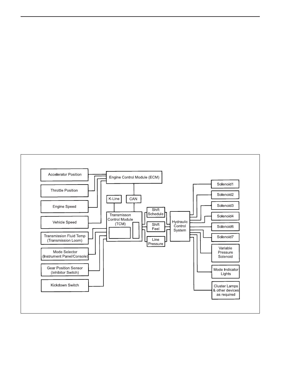
TCM Inputs
To function correctly, the TCM requires engine speed,
vehicle speed, transmission fluid temperature, throttle
position, gear position and Kickdown Switch inputs to
determine the variable pressure solenoid current ramp
and on/off solenoid states.
KAA5A030
This ensures the correct gear selection and shift feel
for all driving conditions.
The inputs required by the TCM are as follows;