Chrysler Cirrus, Dodge Stratus, Plymouth Breeze Haynes. Manual - part 26


  Index      Manuals     Chrysler Cirrus, Dodge Stratus, Plymouth Breeze Haynes (1995-2000). Repair Manual


Search            


Content   ..  24  25  26  27   ..


Chrysler Cirrus, Dodge Stratus, Plymouth Breeze Haynes. Manual - part 26


8-6

Chapter 8 Clutch and driveaxles

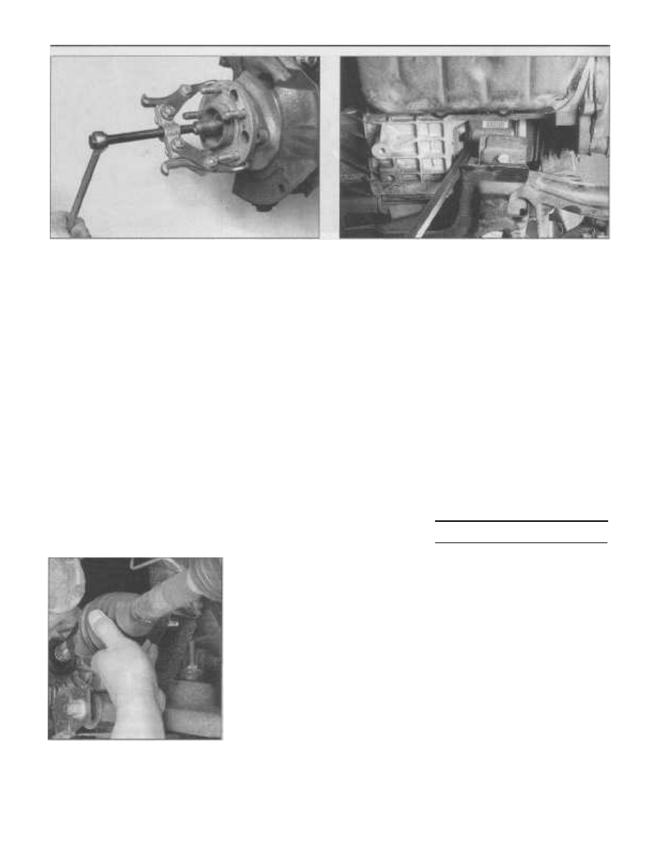
8.8c If the penetrating oil and hammer technique prove

unsuccessful, use a two-jaw puller to push the driveaxle from

the wheel hub

8.10 Insert a prybar between the tripod joint housing and the

transaxle. Pry on the driveaxle until you feel the retaining circlip

on the driveaxle disengage from the differential side gear

trating oil to the hub splines, install the hub nut
on a few turns and strike the end of the
driveaxle with a soft-faced hammer to break it
loose (see illustration). DO NOT attempt to
drive the driveaxle stub out of the wheel hub
using a hammer! In some cases it may be nec-
essary to push the driveaxle stub out of the
hub using a two-jaw puller (see illustration).

9

Before you remove the driveaxle from

the transaxle, check for lubricant leakage in
the area around the driveaxle oil seal. If
there's evidence of a leak, you'll want to
replace the seal after removing the driveaxle
(see Chapter 7, Part A).

10

To remove the driveaxle from the

transaxle, position a prybar against the inner
tripod joint housing and carefully pry it out
until the retaining snap-ring on the driveaxle
is disengaged from the transaxle side gear
(see illustration).
11

While supporting the driveaxle, pull

straight out on the tripod joint housing to
avoid damaging the driveaxle seal located in
the transaxle (see illustration). Caution: Pull
on the tripod housing only! DO NOT pull on

8.11 To avoid damaging the transaxle oil

seal, support the ends of the driveaxle and

pull it straight out

the axleshaft - the only thing keeping the axle-
shaft and tripod housing together is the seal-
ing boot - pulling on the axleshaft might 
sepa-
rate the tripod joint and result in component
damage. 
Remove the driveaxle assembly
from the vehicle.
12

Should it become necessary to move

the vehicle while the driveaxle is removed,
before installing the wheel, place a large bolt
(approximately the same size as the driveaxle
splined shaft) with two large washers (one on
each side of the hub) through the hub and
tighten the nut to 180 ft-lbs. This will prevent

the hub/wheel bearing from separating when
the vehicle weight is placed on the wheel

hub/bearing assembly.
13 If you noted evidence of a leaking
driveaxle seal, refer to Chapter 7A for the seal
replacement procedure.

Installation

14 Installation is the reverse of removal, but

with the following additional points:

Thoroughly clean the driveaxle splines

and hub/bearing shield.

Clean the

respective areas around the driveaxle oil
seal and the steering knuckle/hub splines.
Install a new snap-ring on the inner
driveaxle splines.

c) Lubricate the driveaxle oil seal, tripod

joint splines and sealing surface with the

appropriate transmission lubricant (see
Chapter 1).
When installing the driveaxle into the
transaxle, hold it straight out and push it
in sharply to seat the driveaxle snap-ring
into the groove in the transaxle side

gear. To make sure the circlip is properly
seated, grasp the tripod joint housing

(not the driveaxle) and attempt to pull it
out of the transaxle by hand.

Before installing the driveaxle into the
hub/steering knuckle, lubricate the
driveaxle outer splines with a light coat
of multi-purpose 
grease. After installing

the driveaxle, install the driveaxle/hub

nut and tighten the nut securely but not

to the specified torque at this time.
Tighten the lower control arm balljoint

nut (see Chapter 10) and brake caliper
guide pins (see Chapter 9) to the torque
listed in the Specification Section in their
respective Chapters.
Install the wheel and lug nuts then lower

the vehicle.
On 
1995 through 1999 models, tighten

the driveshaft/hub nut to the torque
listed in this Chapter's Specifications.
Install the spring washer, lock washer
and new cotter pin. Bend the 
ends
around the nut - not over it. On 2000
models, 
use a new driveshaft/hub nut
and tighten it to the torque listed in this
Chapter's Specifications.

i) Tighten the wheel lug nuts to the torque

listed in the Chapter 1 Specifications.

I)

Check and add transaxle/differential
lubricant as applicable (see Chapter 1).

9

Driveaxle boot replacement

Note 1: If the CV joints are damaged (usually
due to torn boots), individual replacement

parts are not available. The complete driveaxle.
new or rebuilt, must be replaced 
as an assem-
bly and are available on an exchange basis.

Note: 2: On 1995 to 1997 models, the only

serviceable part on the outer CV joint is the
hub/bearing shield which is pressed onto the
outer CV joint housing splined shaft. The
outer CV joint cannot be removed from the
axleshaft. In the event of bearing or sealing
boot failure on these models, the entire
driveaxle must 
be replaced.

Outer joint boot (1998 and
later models only)

Disassembly

Refer to illustrations 9.2, 9.4, 9.5a and 9.5b
1

Remove the driveaxle from the vehicle

(see Section 8).
2

Mount the driveaxle in a vise with soft

a)

b)

d)

e)

f)

g)

h)

Chapter 8 Clutch and driveaxles

8-7

9.2 Cut the boot clamps and remove them

from the driveaxle

jaws (to prevent damage to the axleshaft).

Check the CV joint for excessive play in the
radial direction, which indicates worn compo-
nents. Check for smooth operation through-
out the full range of motion for the CV joint.
Using diagonal cutters, cut the boot clamps
and remove them (see illustration).
3

Before separating the outer CV joint

from the axleshaft assembly, mark the CV
joint housing to the axleshaft so they may be

reinstalled in the same position.

4

Pry up on the edge of the boot and pull

it off the outer CV joint housing (see illustra-

tion).
5

Using a soft-faced hammer, carefully

drive the outer CV joint off the axleshaft by
striking the outer housing (only) - be careful
not to damage the splines or the cage (see
illustrations).
6

Remove the large retaining circlip from

the axleshaft then slide off the sealing boot.

Check

7

Clean the CV joint thoroughly with sol-

vent to remove all grease. Blow the solvent
out of the joint with compressed air, if avail-
able. Warning: Wear eye protection! Check

9.4 Remove the boot from the

CV joint housing

for cracks, pitting, scoring and other signs of
wear.
8

If there's any evidence of damage or

excessive wear, replace the outer CV joint as
an assembly. The outer CV joint is not ser-
viceable.

Installation

Refer to illustrations 9.10, 9.12 and 9.14
9

Pack the CV joint with half of the special

CV joint grease included in the boot kit.
10

Wrap the splined end of the axleshaft

with tape to protect the new boot from dam-

age during installation (see illustration).
Install the new small clamp and new boot
onto the axleshaft.
11

Remove the tape from the splines and

install the large retaining circlip. Place the
remaining CV joint grease into the sealing
boot.
12 Install the CV joint assembly onto the

axleshaft aligning the previously applied
match-marks. Using a brass hammer, seat
the joint onto the shaft (see illustration).

Make sure the CV joint assembly is locked

into position on the axleshaft by trying to pull
it off by hand.

9.5a Use a soft-faced hammer to

disengage the outer CV joint from the

axleshaft retaining circlip .. .

9.5b . . . and remove the outer CV joint

from the axleshaft

13

Wipe any excess grease from the axle

boot groove on the CV joint housing. Seat the
small diameter of the boot in the recessed
area on the axleshaft. Push the other end of

the boot onto the CV joint housing and move

9.10 Before installing the boot, wrap the axleshaft splines with

tape to prevent damaging the boot

9.12 Install the outer CV joint onto the axleshaft, then use a brass

drift and a hammer to seat the CV joint on the axleshaft

8-8

Chapter Clutch and driveaxles

9.14 Tighten the boot clamps using special plier-type crimpers,

which are available at most auto parts stores

9.24 Once the boot is detached from the tripod housing, the joint

can be separated

the race in or out until there's no deformation
(distortion or dents) in the boot.
14 Install the large clamp onto the sealing
boot. Secure the sealing boot to the axleshaft
and CV joint housing using a special clamp
crimping tool as shown (see illustration).
These special plier-type crimpers are avail-
able at most auto parts stores. Place the
crimping tool over the bridge of the clamp
and squeeze it together until the tool is fully
closed.
15 Install the driveaxle (see Section 8).

Outer CV joint hub/bearing

shield

Replacement
16

Remove the driveaxle from the vehicle

(see Section 8).
17

Mount the driveaxle in a vise with soft

jaws (to prevent damage to the axleshaft).

18

Using a drift and hammer, carefully and

evenly drive the hub/bearing shield off the
outer CV joint shaft.

19

Place the shield onto the axleshaft with

the large diameter facing up. Using an appro-

priate size section of pipe and a hammer,

drive the shield onto the axleshaft. Be careful

not to cock the hub/bearing shield. Drive it
onto the shaft until it is fully seated.

20 Install the driveaxle onto the vehicle (see
Section 8).

Inner joint boot

Disassembly

Refer to illustrations 9.24, 9.25, 9.26 and 9.27
21

Remove the driveaxle from the vehicle

(see Section 8).
22

Mount the driveaxle in a vise with soft

jaws (to prevent damage to the axleshaft).
Check the CV joint for excessive play in the
radial direction, which indicates worn compo-
nents. Check for smooth operation through-
out the full range of motion for the CV joint.
23

Before separating the tripod housing

from the axleshaft assembly, use a center-
punch or equivalent to match-mark the hous-
ing to the axleshaft so they may be reinstalled
in the same position.
24

After removing the boot clamps (see

illustration 9.2), pull the boot back from the
tripod housing and slide the it off the spider
assembly (see illustration). Caution: Hold
onto the spider 
assembly bearings as you

remove the housing to prevent them from

falling off. If necessary, wrap some tape
around them to secure them in position.
25

Use a centerpunch to mark the spider to

the axleshaft so that they can be reassem-
bled in the same position (see illustration).
26

Remove the snap-ring from the end of

the axleshaft with a pair of snap-ring pliers
(see illustration).
27

Use a hammer and a brass drift to drive

the spider assembly from the driveaxle and
then remove the old sealing boot (see illus-
tration). 
Be careful not to strike the spider

assembly bearings.

Check

28

Clean all components with solvent to

remove the grease, and check for cracks, pit-

ting, scoring and other signs of wear.

Replacement parts for these driveaxles are
not available, so if any component exhibits

damage, the entire driveaxle must be
replaced.

Reassembly

Refer to illustration 9.34
Caution: The inner tripod joint sealing boots
on the vehicles covered in this manual are
constructed from different materials for differ-

9.25 Use a centerpunch to mark (arrows) the tripod spider

to the axleshaft

9.26 Remove the spider retaining snap-ring from the end of the

axleshaft

Chapter 8 Clutch and driveaxles

8-9

9.27 Carefully drive the tripod spider assembly from the axleshaft

using a brass drift and hammer - make sure you don't damage the

bearing surfaces or the splines on the axleshaft

9.34 Equalize the pressure in the boot by inserting a small, dull

screwdriver between the boot and the joint housing

ent temperature applications. High-tempera-
ture applications use silicone rubber that is
soft and pliable. Standard temperature appli-
cations use Hytrel plastic that is stiff and rigid.
The replacement 
boots must be the same
type of material as the sealing boot that was
removed.
29

Wrap the splined end of the axleshaft

with tape to protect the new boot from dam-
age during installation (see illustration 9.10).
Install the new small clamp and new sealing
boot onto the axleshaft. Remove the tape

from the splines.

30 Install the spider assembly onto the
axleshaft aligning the centerpunch match-
marks (see illustration 9.25). Install the

snap-ring onto the axleshaft. Note: The snap-
ring must be fully seated in it's groove. If nec-
essary, use a hammer and brass drift to fully

seat the spider assembly on the axleshaft. Be
careful not to strike the spider assembly 
bear-
ings.
31

Pack the tripod joint housing with half of

the special CV joint grease included in the
boot kit. Place the remaining CV joint grease
into the sealing boot.
32

Place the tripod housing onto the axle-

shaft assembly aligning the previously
applied match-marks.
33

Slide the sealing boot into place, making

sure both ends seat in their grooves.
34

Next, insert a small DULL screwdriver or

other small blunt object between the tripod
housing and the sealing boot (see illustra-

tion). This will equalize the pressure in the

boot during positioning of the axleshaft in the

tripod outer housing. Caution: DO NOT dam-
age the sealing boot during this procedure!

35

With the sealing boot vented using the

screwdriver (or equivalent), position the axle-
shaft so it is in the middle of it's axial travel
within the tripod housing. Make sure there
are no creases or dents in the sealing boot
after positioning the axleshaft. Remove the
screwdriver from between the housing and
sealing boot.
36 Install the large clamp onto the sealing
boot. Secure the sealing boot to the axleshaft
and CV joint housing using a special clamp
crimping tool as shown (see illustration
9.14). 
These special plier-type crimpers are
available at most auto parts stores. Place the
crimping tool over the bridge of the clamp
and squeeze it together until the tool is fully
closed.
37 Install the driveaxle (see Section 8).

8

8-10

Chapter 8 Clutch and driveaxles

Notes

Chapter 9 Brakes

Contents

Section

Section

Anti-lock Brake System (ABS) - general information .............................2

General information........................................................................

1

Brake check ......................................................................See Chapter 1

Master cylinder - removal, installation and fluid

reservoir replacement...............................................................

8

Brake disc - inspection, removal and installation..........................

5

Brake fluid level check......................................................See Chapter 1

Parking brake cables - replacement..............................................

14

Brake hoses and lines - inspection and replacement ....................
Brake system - bleeding ................................................................

10
11

Parking brake lever assembly - removal,

installation and adjustment.......................................................

13

Brake light switch - check, replacement and adjustment ..............

15

Power brake booster - check, removal and installation .................

12

Disc brake caliper - removal and installation .................................

4

Proportioning valves - check and replacement.............................

9

Disc brake pads - replacement ......................................................

3

Wheel cylinder - removal and installation ......................................

7

Drum brake shoes - replacement ..................................................

6

Specifications

General

Brake fluid type ........................................................................................

Disc brakes

Brake pad minimum thickness (metal backing plus lining) .....................
Disc lateral runout limit............................................................................
Disc minimum thickness..........................................................................

Thickness variation ..................................................................................

Drum brakes

Minimum brake lining thickness ..............................................................
Maximum drum diameter........................................................................

Torque specifications

Brake booster mounting nuts ..................................................................
Brake hose banjo bolt-to-caliper .............................................................

Caliper guide pin bolts.............................................................................
Master cylinder-to-brake booster mounting nuts....................................
Wheel cylinder-to-backing plate mounting nuts .....................................
Wheel lug nuts .........................................................................................

See Chapter 1

3/8 inch
0.005 inch
Cast into disc
0.0005 inch

1/8 inch
Cast into drum

Ft-lbs (unless otherwise indicated)
250 in-lbs
35
16
250 in-lbs
97 in-lbs
See Chapter 1

9

9-2

Chapter 9 Brakes

1

General information

General

All models covered by this manual are

equipped with a hydraulically operated brake
system. The front brakes are disc type and
the rear brakes are drum type. Both brake
types are self-adjusting. Disc brakes auto-
matically compensate for pad wear, while
drum brakes incorporate an adjustment
mechanism which is activated as the brakes
are applied.

The hydraulic system is split diagonally -

the left front and right rear brakes are on one
circuit; the right front and left rear on the
other. If one circuit fails, the other circuit will
remain functional and a warning indicator will
illu minate on the dashboard when a substan-

tial amount of brake fluid is lost, showing that

a failure has occurred.

Before disconnecting any electrical con-

nector from a vehicle equipped with an Anti-
lock Brake System (ABS), make sure the igni-

tion is in the OFF position and the negative

battery cable has been disconnected from

the ground stud on the left shock tower (see

Chapter 5, Section 1). If any weld repair is

going to be performed on a vehicle equipped
with an ABS system, disconnect the CAB or

ICU electrical connector (see Section 2) or

damage to the electronics may occur.

Calipers

All disc brakes used by the vehicles

covered in this manual are equipped with a
double-pin floating caliper, a single-piston
design that "floats" on two steel guide pins.
When the brake pedal is depressed,
hydraulic pressure pushing on the piston is
transmitted to the inner brake pad and
against the inner surface of the brake disc. As
the force against the disc from the inner pad
is increased, the caliper assembly moves in,
sliding on the guide pins and pulling the outer
pad against the disc, exerting a pinching
force on the disc.

Master cylinder

The master cylinder is located in the

engine compartment on the power brake
booster, and can be identified by the large

fluid reservoir on top. The master cylinder has
two separate circuits to accommodate the

diagonally split system.

Power brake booster

The power brake booster uses engine

manifold vacuum to provide assistance to the
brakes. It is mounted on the firewall in the

engine compartment, directly behind the
master cylinder.

Parking brake system

The parking brake actuates the rear

brakes via two cables. The parking brake
cables pull on a lever attached to the brake
shoe assembly, causing the shoes to expand
against the drum.

Precautions

There are some general precautions

and warnings related to the hydraulic brake

system:

a) Use only brake fluid conforming to DOT

3 specifications.

b) The brake pads and linings may contain

asbestos fibers which are hazardous to
your health if inhaled. Whenever you
work on brake system components, DO
NOT blow it out with compressed air
and DO NOT inhale it. DO NOT use
gasoline or petroleum-based solvents to
clean components. Brake system
cleaner should be used to flush the dust
into a drain pan. After the brake compo-
nents are cleaned, dispose of the con-
taminated rags and cleaner in a 
labeled,
covered container. Do not allow the fine
dust 
to become airborne.

c) Safety should be paramount whenever

any servicing of the brake components
is performed. Do not use parts or fas-
teners which are not in perfect condi-
tion, and be 
sure all clearances and
torque specifications are adhered 
to. If

you are at all unsure about a certain
procedure, seek professional advice.

Upon completion of any brake system
work, 
test the brakes carefully in a con-
trolled 
area before driving the vehicle in
traffic.

d) If a problem is suspected in the brake

system, don't drive the vehicle until it's
been corrected.

2

Anti-lock Brake System (ABS) -
general information

Description

1

The Anti-lock Brake System (ABS) pre-

vents wheel lock-up on virtually any road sur-
face. Preventing the wheels from locking up
maintains vehicle maneuverability, preserves
directional stability, and allows optimal decel-
eration on all surfaces. How does ABS work?
Basically, by monitoring the rotational speed
of the wheels and controlling the brake line
pressure to the calipers/wheel cylinders at
each wheel.

Components

Controller Anti-lock Brake (CAB)

Refer to illustration 2.2
2

The CAB consists of a pair of micropro-

cessors which monitor wheel speeds and
control the anti-lock and traction control

functions. The CAB receives two identical

signals and process the information indepen-

dently of one another. The results are com-

pared to make sure that they agree. If they

don't, the CAB turns off the ABS and traction
control functions, and turns on the warning

li ghts. The CAB is located in the engine com-

partment on the right hand side and mounted
near the windshield washer fluid and coolant
reservoirs (see illustration).

2.2 The Controller Anti-lock Brake (arrow)

is the brain of the ABS system (1997 and

earlier style shown; on 1998 models,

the CAB is mounted on the HCU

Hydraulic Control Unit (HCU)

Refer to illustration 2.3
3

The Hydraulic Control Unit (HCU) is

located in the engine compartment on the
right hand side and mounted to the front sus-
pension crossmember (see illustration). The
HCU contains the valve block assembly, fluid
accumulators, the pump/motor assembly and
relay box.

Integrated Control Unit (ICU) - 1998
models only

4

On 1998 models a new ABS brake sys-

tem was introduced which functions very
much like the previous ABS system except it
combines the HCU and CAB into one unit,
called the Integrated Control Unit (ICU). The
ICU is located in the same location as the
HCU on previous models (see above).

Valve block assembly

5

The valve block assembly contains eight

valve/solenoids: four inlet valves and four

outlet valves. The inlet valves are spring-
loaded in the open position and the outlet

valves are spring-loaded in the closed posi-
tion. During ABS operation, these valves are
cycled to maintain the proper slip ratio for
each channel. If a wheel locks, the inlet valve

is closed to prevent a further increase in

pressure. Simultaneously, the outlet valve is
opened to release the pressure back to the
accumulators until the wheel is no longer
slipping. Once the wheel no longer slips, the
outlet valve closes and the inlet valve opens
to allow pressure to the wheel caliper or
wheel cylinder.

Pump/motor assembly

6

The pump/motor assembly consists of

an electric motor and a dual-piston pump.
The pump provides high-pressure brake fluid
to the hydraulic control unit when the ABS
system is activated.

Fluid accumulators

7

The two fluid accumulators located

inside the HCU are for the primary and sec-
ondary hydraulic circuits. The accumulators

Chapter 9 Brakes

9-3

2.3 The Hydraulic Control Unit (arrow) is located

below the power steering pump

2.9 Wheel Speed Sensor (arrow)

temporarily store brake fluid that is blocked
during ABS operation. This fluid is re-routed
to the pump.

Proportioning valves

8

Refer to Section 9 for a description of

the proportioning valves.

Wheel Speed Sensors (WSS)

Refer to illustration 2.9
9

A speed sensor is mounted at each

wheel (see illustration). The speed sensors
send variable voltage signals to the HCU.
These analog voltage outputs are propor-
tional to the speed of rotation of each wheel.

Diagnosis and repair

10

The ABS system has self-diagnostic

capabilities. Each time the ignition key is

turned to ON, the system runs a self-test. If it
finds a problem, the ABS and traction control
warning lights come on and remain on. If
there's no problem with the system, the lights
go out after a second or two.

11

If the ABS and traction control warning

li ghts come on and stay on during vehicle

operation, there is a problem in the ABS

system. Two things now happen: The con-
troller stores a diagnostic trouble code (which
can be displayed with a DRB II scanner at the
dealer) and the ABS system is shut down.
Once the ABS system is disabled, it will
remain disabled until the problem is cor-
rected and the trouble code is erased. How-
ever, the regular brake system will continue
to function normally.

12

Although a DRB II scan tool (a special

electronic tester) is necessary to properly
diagnose the system, you can make a few
preliminary checks before taking the vehicle
to a dealer or other shop for service:

a) Make sure the brake calipers and wheel

cylinders are in good condition.

b) Check the electrical connector at the

CAB, HCU or ICU as applicable.

c) Check the fuses.
d) Follow the wiring harness to the wheel

speed sensors and brake light switch

and make sure all connections are clean,
secure and the wiring isn't damaged.

If the above preliminary checks don't

rectify the problem, the vehicle should be
diagnosed by a dealer service department or
other qualified repair shop.

3

Disc brake pads - replacement

Refer to illustrations 3.2, 3.3, 3.4a through 3.41
Warning: Disc brake pads must be replaced
on both front wheels at the 
same time - never
replace the pads on only one wheel. Also, the
dust created by the brake system may con-

tain asbestos, which is harmful to your health.

Never blow it out with compressed air and
don't inhale any of it. An approved filtering
mask should be worn when working on the
brakes. Do not, under any circumstances, use
petroleum-based solvents to clean brake
parts. Use brake system cleaner only!

1

Loosen the front wheel lug nuts 1/4-

turn, raise the front of the vehicle and support
it securely on jackstands. Apply the parking
brake. Remove the front wheels.
2

Using a syringe or equivalent, siphon

approximately two-thirds of the fluid from the
master cylinder reservoir and discard it. Posi-
tion a drain pan under the brake assembly
and clean the caliper and surrounding area
with brake system cleaner (see illustration).
3

Push the piston back into its bore using

a C-clamp (see illustration). As the piston is

9

3.2 Always wash the brakes with brake system

cleaner before working on them

3.3 Use a C-clamp to press the caliper piston into its bore


Content   ..  24  25  26  27   ..