Chrysler Cirrus, Dodge Stratus, Plymouth Breeze Haynes. Manual - part 24


  Index      Manuals     Chrysler Cirrus, Dodge Stratus, Plymouth Breeze Haynes (1995-2000). Repair Manual


Search            


Content   ..  22  23  24  25   ..


Chrysler Cirrus, Dodge Stratus, Plymouth Breeze Haynes. Manual - part 24


7A-4

Chapter 7 Part A Manual transaxle

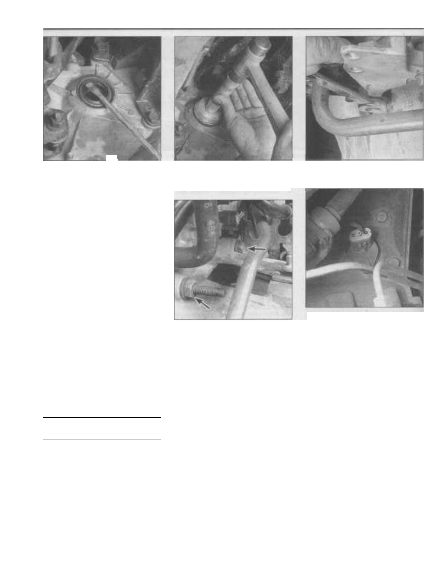
5.6 Using a seal driver, large section of

pipe or a large deep socket as a drift,

drive the new seal squarely into the bore

and make sure that it's completely seated

6.8 Remove the intake manifold

support bracket

6.9 Remove the upper clutch housing

fasteners (arrows)

6.10 The Vehicle Speed Sensor is located

on the transaxle next to the rear

engine mount

5.4 Using a large screwdriver or prybar,

carefully pry the oil seal out of the

transaxle (if you can't remove the oil seal

with a screwdriver or prybar, you may

need to obtain a special seal removal tool,

available at most auto parts stores, to do

the job)

inner ends of the driveaxles mate with the dif-

ferential side gears. If you suspect that one of
these seals is leaking, raise the vehicle and
support it securely on jackstands. If a seal is

in fact leaking, you'll see a trail of wet lubri-

cant on the side of the transaxle below the
seal.
3

Remove the driveaxle (see Chapter 8).

4

Using a large screwdriver or prybar,

carefully pry the oil seal out of the transaxle
(see illustration).
5

If you can't remove the oil seal with a

screwdriver or pry bar, you may need to
obtain a special seal removal tool (available
at most auto parts stores) to do the job.
6

Using a seal driver, large section of pipe

or a large deep socket as a drift, install the
new oil seal (see illustration). Drive it into the
bore squarely and make sure that it's com-
pletely seated. Lubricate the driveaxle oil
seal, tripod joint splines and sealing surface
with the appropriate transmission fluid (see
Chapter 1).
7

Install the driveaxle (see Chapter 8). Be

careful not to damage the lip of the new seal
during installation.

6

Manual transaxle - removal and

installation

Note 1: This procedure requires the removal
of all engine mounts except 
for the right side
engine mount. If the vehicle must be moved

after the transaxle has been removed, make
sure the engine is supported at all times and

the appropriate sized bolts and nuts are

installed in the front wheel hub/bearings (refer

to Chapter 8).
Note 2: There are four different gear ratios

available with this transaxle. If you are going

to replace this transaxle or obtain a rebuilt

unit, check the metal identification tag

mounted to the rear cover before purchasing
a new or rebuilt transaxle to ensure you're
getting the correct gear ratio for your particu-
lar application.

Removal

Refer to illustrations 6.8, 6.9, 6.10, 6.16, 6.17,
6.18, 6.19, 6.28 and 6.31

1

Open the hood and place protective

covers on the front fenders and cowl. Special
fender covers are available, but an old bed-
spread or blankets will also work.
2

Disconnect the negative battery cable

from the ground stud on the left shock tower
(see Chapter 5, Section 1).
3

Remove the air cleaner assembly (see

Chapter 4).
4

Disconnect the clutch cable from the

release lever (see Chapter 8).
5

Disconnect the shift cables from the

transaxle and detach the cable bracket (with
cables attached) from the transaxle (see Sec-
tion 2). Position the cables out of the way.
6

Detach the accelerator cable and cruise

control cable (if equipped) from the throttle

lever (see Chapter 4 if necessary).
7

Detach the accelerator/cruise control

cable bracket from the throttle body (with
cables attached) and position it out of the

way.

8

Remove the intake manifold support

bracket (see illustration).

9

Remove the upper clutch housing bolts

(see illustration).
10

Disconnect the electrical connectors

from the vehicle speed sensor (see illustra-
tion) 
and back-up light switch (see illustra-
tion 4.1).

11

Loosen the driveaxle hub nuts (see

Chapter 8) and front wheel lug nuts. Raise the
vehicle and place it securely on jackstands.

Remove both front wheels.
12

Drain the transaxle fluid (see Chapter 1).

13

Remove the driveaxles (see Chapter 8).

14

Remove the starter motor (see Chap-

ter 5).

15

Remove the splash shield/battery cover

from the left front wheel well (see Chapter 5).

Extract the push-in fasteners and remove the

transaxle splash shield.

16

On 1998 models, remove the oil pan-to-

Chapter 7 Part A Manual transaxle

7A-5

6.16 Oil pan-to-transaxle structural collar

assembly details - 1998 models only

transaxle structural collar and transaxle

clutch housing lower cover (see illustration).
17

On all models except 1998, remove the

transaxle lateral strut and clutch housing

lower cover (see illustration).
18 If the modular clutch assembly is to be
reinstalled, match-mark the clutch assembly

to the driveplate (see illustration).

19

Remove the four modular clutch assem-

bly-to-driveplate bolts (see illustration). To
gain access to each bolt, rotate the engine
clockwise (ONLY) as viewed from the drive-
belt end of the engine using the crankshaft
damper/pulley bolt. Remove all four bolts and
discard them. Use a screwdriver placed in

the ring gear of the driveplate to keep the
crankshaft from turning during removal of the

bolts.

20

After removing the clutch module

mounting bolts, push the modular clutch

assembly into the transaxle clutch housing as
far as possible.
21

Remove any exhaust components

6.17 Remove the lateral strut (lower

arrow) and clutch housing lower cover

(upper arrow) - all except 1998 models

which will interfere with transaxle removal
(see Chapter 4).
22

Remove any remaining chassis or sus-

pension components which will interfere with

transaxle removal. Caution: If the front sus-
pension crossmember has 
to be repositioned

to facilitate transaxle removal, it must be

match-marked to the body and frame (see

Chapter 10) to maintain proper wheel align-

ment at reassembly.
23

Support the engine from above with a

hoist, or place a floor jack under the oil pan.
Place a wood block on the jack head to
spread the load on the oil pan.

24

Remove the left engine mounting

bracket from the transaxle (see Chapter 2A).
25

Remove the front engine mounting

bracket and strut (see Chapter 2A).

26

Remove the rear engine mounting

bracket (see Chapter 2A).

27

Remove the engine support module (1995

through 1997 models) or front and rear lower

engine mounts (1998 and later models) as
applicable (see Chapter 2A). Note: The engine

support module is attached to the lower radia-

tor support. When removing the engine support

module, the radiator and air conditioning con-
denser (if equipped) must 
be supported.

6.18 Match-mark the modular clutch

assembly to the driveplate

6.19 Rotate the engine clockwise using

the crankshaft damper/pulley bolt and

remove the four flywheel-to-clutch

assembly bolts

28

Support the transaxle with a transmis-

sion jack, if available, or use a floor jack (see
illustration). 
Secure the transaxle to the jack
using straps or chains so it doesn't fall off
during removal.
29

Remove the lower transaxle clutch

housing-to-engine bolts. Make sure all clutch

7A

6.28 Place a jack under the transaxle (transmission jack shown)

and secure the transaxle to the jack using chains or straps

6.31 While removing the transaxle from the engine, make sure to

keep it level so the modular clutch assembly doesn't fall off the

transaxle input shaft

7A-6

Chapter 7 Part A Manual transaxle

housing-to-engine bolts are removed.
30

Make a final check that all wires, hoses

and brackets have been disconnected from
the transaxle, then with the engine properly
supported, separate the transaxle from the
engine.
31

Carefully lower the transaxle and

remove it from under the vehicle (see illus-
tration). 
Make sure you keep the transaxle
level as you maneuver it or the modular
clutch assembly may fall out. Note: Rein-

stalling the clutch housing lower cover after

the transaxle clears the flywheel will help hold
the clutch 
assembly in place.
32

Remove the modular clutch assembly

from the transaxle. Handle it carefully to
avoid contaminating the friction surfaces.
Inspect it for excessive wear or contamina-

tion (see Chapter 8). In most cases, because

of the time and labor involved in gaining
access to the clutch assembly, it should be
replaced whenever the transaxle is removed
or replaced unless its in new or near-perfect
condition.

33

Check the crankshaft rear main seal for

evidence of leakage. If replacement is neces-
sary, refer to Chapter 2A.

Installation

34 Install the modular clutch assembly onto
the transaxle input shaft. Handle it carefully
to avoid contaminating the friction surfaces.
35

With the transaxle secured to the jack,

raise it into position and carefully slide it for-
ward until the clutch housing seats against
the engine. Do not use excessive force to
install the transaxle - if it doesn't slide into
place easily, readjust the angle of the
transaxle and try again. Make sure you keep
the transaxle level as you maneuver it or the
modular clutch assembly may fall out. Do not
force it or use the clutch housing bolts to pull
it together. Make sure the dowel pins on the
engine are aligned with their respective holes
in the transaxle. If you are experiencing diffi-
culty, solicit the aid of an assistant.
37 Install the clutch housing-to-engine
bolts with brackets and clamps where
required and tighten them to the torque listed
in this Chapter's Specifications.
38 Install the engine support module (1995
through 1997 models) or front and rear lower
engine mounts (1998 and later models) as
applicable (see Chapter 2A).
39 Install the rear engine mounting bracket

to the transaxle and secure it to the engine

support module (1995 through 1997 models)
or rear lower engine mount (1998 and later
models) as applicable (see Chapter 2A).

Tighten the bracket-to-engine bolts (ONLY)
to the torque listed in the Specification Sec-
tion of Chapter 2A. Leave the through-bolt

loose for now.

40 Install the front engine mounting bracket
and strut (see Chapter 2A). Secure the

bracket to the engine support module (1995

through 1997 models) or front lower engine
mount (1998 models) as applicable (see
Chapter 2A). Tighten the mounting bracket

and strut-to-engineltransaxle bolts (ONLY) to
the torque listed in the Specification Section
of Chapter 2A. Leave the through-bolt loose
for now.
41

Install the left engine mounting bracket

onto the transaxle and secure it to the sup-
port assembly on the frame rail (see Chap-
ter 2A). Tighten the bolts to the torque listed
in the Specification Section of Chapter 2A.
42

Tighten the front and rear engine mount

through-bolts to the torque listed in the
Specification Section in Chapter 2A.
43

Remove the engine and transaxle sup-

port jacks.
44 If you're reinstalling the old modular
clutch assembly, align the driveplate-to-modu-
lar clutch assembly match-marks applied in
Step 18. Install four new driveplate-to-modular
clutch bolts. DO NOT install the old bolts - they
are one-time use only. To gain access to each
bolt hole, rotate the engine clockwise (ONLY)
as viewed from the drivebelt end of the engine
using the crankshaft damper/pulley bolt.
Tighten the driveplate-to-modular clutch
assembly bolts in a criss-cross pattern to the
torque listed in the Specification Section of
Chapter 8. Use a screwdriver placed in the ring
gear of the driveplate to keep the crankshaft

from turning during installation of the bolts.

45 Install the clutch housing lower cover.

Tighten the bolts to the torque listed in this

Chapter's Specifications.
46

On all models except 1998 and later,

install the lateral strut bracket (see illustra-

tion 6.17). Tighten the bolts to the torque

li sted in this Chapter's Specifications.

47

On 1998 models, install the oil pan-to-

transaxle structural collar. Tighten the bolts
to the torque listed in the Specification Sec-
tion of Chapter 2A.
48

Attach the electrical connectors to the

vehicle speed sensor and back-up light
switch.
49 Install the transaxle splash shield and
secure it with the push-in fasteners. Install
the splash shield/battery cover into the left
front wheel well (see Chapter 5).
50 Install the starter motor (see Chapter 5).
Tighten the bolts to the torque listed in the
Specification Section of Chapter 5.
51

Install any chassis or suspension com-

ponents that were removed. Caution: If the
front suspension crossmember was reposi-
tioned to facilitate transaxle removal, it must
be aligned with the previously applied 
match-
marks on the body and frame (see Chap-
ter 10) to maintain proper wheel alignment.
52 Install any exhaust components that
were removed (see Chapter 4).
53 Install the driveaxles, hub nuts and front
wheels (see Chapter 8).
54 Install the intake manifold support
bracket (see illustration 6.8).
55 Install the accelerator and cruise control
(if equipped) cable bracket onto the throttle
body and tighten the bolts securely.
56 Install the accelerator and cruise control
(if equipped) cable ends into the throttle
lever.
57 Install the shift cables and mounting

bracket onto the transaxle (see Section 2).

Tighten the shift cable bracket bolts to the to
the torque listed in this Chapter's Specifica-
tions.

58

Attach the clutch cable onto the clutch

release lever and install the inspection cover
(see Chapter 8).
59

Attach the negative battery cable to the

ground stud on the left shock tower.

60

Adjust the shift crossover cable (see

Section 2).
61

Install the air cleaner assembly (see

Chapter 4).
62

Fill the transaxle with the appropriate

fluid (see Chapter 1). Road test the vehicle
and check for proper transaxle operation and
fluid leaks. Shutoff the engine and recheck
the transaxle fluid level.

7

Manual transaxle overhaul -

general information

1

Overhauling a manual transaxle is a diffi-

cult job for the do-it-yourselfer. It involves the
disassembly and reassembly of many small
components. Numerous clearances must be
precisely measured and, if necessary,
changed with select fit spacers and snap-
rings. As a result, if transaxle problems arise,
it can be removed and installed by a compe-
tent do-it-yourselfer, but overhaul should be
left to a dealer service department or other
qualified transmission repair shop. Rebuilt
transaxles may be available - check with your
dealer parts department or local auto parts
stores. At any rate, the time and money
involved in an overhaul is almost sure to
exceed the cost of a rebuilt unit.
2

Nevertheless, it's not impossible for an

inexperienced mechanic to rebuild a trans-
axle if the special tools are available and the

job is done in a deliberate step-by-step man-

ner so nothing is overlooked.

3

The tools necessary for an overhaul

include internal and external snap-ring pliers.

a bearing puller, a slide hammer, a set of pin

punches, a dial indicator and possibly a
hydraulic press. In addition, a large, sturdy

workbench and a vise or transaxle stand will

be required.

4

During disassembly of the transaxle,

make careful notes of how each piece comes
off, where it fits in relation to other pieces and
what holds it in place - actually noting how
they are installed when you remove the parts
will make it much easier to put it back
together. If necessary take photographs dur-
ing disassembly. Note: The output shaft can-
not be disassembled.
5

Before taking the transaxle apart for

repair, it will help if you have some idea what
area of the transaxle is malfunctioning. Cer-
tain problems can be closely tied to specific
areas in the transaxle, which can make com-
ponent examination and replacement easier.
Refer to the Troubleshooting Section at the
beginning of this manual for information
regarding possible sources of trouble.

Chapter 7 Part B

Automatic transaxle

Contents

Section

Automatic transaxle - removal and installation ......................................9
Automatic transaxle fluid and filter change...................... See Chapter 1
Automatic transaxle fluid level check ............................... See Chapter 1
Diagnosis - general ................................................................................ 2
Oil seal - replacement............................................................................3
General information................................................................................1
Park/Neutral/Back-up light switch - check and replacement ................6

Section

Shift cable - removal, installation and adjustment.................................4
Gearshift assembly - replacement.........................................................5

Shifter/ignition interlock system - description, check

and cable replacement..................................................................... 7

Transaxle mount................................................... See Chapter 2A or 2B
Transmission Control Module - removal and installation...................... 8

Specifications

General

Transaxle type.........................................................................................
Fluid type and capacity...........................................................................

Torque specifications

Cooler line fittings....................................................................................
Bellhousing lower cover bolts ..................................................................
Driveplate-to-torque converter bolts.......................................................
Park/Neutral/Back-up light switch...........................................................
Transaxle bellhousing-to-engine bolts ....................................................

41TE
See Chapter 1

Ft-lbs (unless otherwise indicated)

105 in-lbs
105 in-lbs

55
25
70

7B

1

General information

The vehicles covered by this manual are

equipped with either the NV T350 (A-578) 5-
speed manual or the 41TE 4-speed auto-
matic transaxle. Information on the automatic
transaxle is included in this part of Chapter 7.
Service procedures for the manual transaxle
are contained in Chapter 7, Part B.

The automatic transaxle and the differ-

ential are housed in a compact, lightweight,
two-piece aluminum alloy housing. Operation
of the transaxle is controlled electronically by
the Transmission Control Module (TCM)
which is the "brain" of the transaxle. The

TCM monitors engine and transaxle operat-

ing parameters through numerous sensors
and then generates output signals to various
relays and solenoids to regulate hydraulic

pressures, optimize driveability, provide effi-
cient torque management and maintain maxi-
mum fuel economy. The TCM is part of the
On-Board Diagnostic system OBD-II. For
more information see Chapter 6. Note: If the

power has been interrupted (battery discon-

nected or has failed) the transaxle will shift
roughly for the first few 
gear progressions
while the TCM relearns the engine and
transaxle parameters.

The Sections in this Chapter instruct you

on how to replace and adjust those parts of
the transaxle that can be easily serviced at
home, as well as how to remove and install

the transaxle itself. Because of the complex-

ity of the transaxle rotating machinery, elec-

tronic operating system and the special tools

required to diagnose and service it properly,
we don't recommend repairing the transaxle
at home. For service and repairs outside the

scope of this manual, take the vehicle to a
dealer service department or other qualified
transmission repair shop.

Some models came equipped with a

driver-interactive option called "Autostick."
This system allows the transaxle to be shifted
manually. When the shift lever is placed in the
Autostick position, the transaxle will remain in
whatever gear it was using before Autostick
was activated. Moving the shift lever to the
left (towards the driver) causes the transaxle
to downshift and moving it to the right
(towards the passenger seat) causes it to
upshift. The instrument cluster displays the
gear you have selected by illuminating a box
around the gear currently engaged. In the
Autostick mode the vehicle can be driven
away in 1st, 2nd or 3rd gear. The speed
(cruise) control system can be used while in
the Autostick mode as long as the shift lever

7B-2

Chapter 7 Part B Automatic transaxle

is in 3rd or 4th gear. However, when the shift
lever is moved to 2nd gear the speed control
system is disengaged. Shifting into Overdrive
cancels the Autostick mode and the TCM
resumes controlling transaxle operation.

2

Diagnosis - general

1

Automatic transaxle malfunctions may

be caused by five general conditions:

a) Poor engine performance
b) Improper adjustments
c) Hydraulic malfunctions
d) Mechanical malfunctions
e) Malfunctions in the computer or its sig-

nal network

2

Diagnosis of these problems should

always begin with a check of the easily
repaired items: fluid level and condition (see
Chapter 1), shift cable adjustment and shift
lever installation. Next, perform a road test to
determine if the problem has been corrected
or if more diagnosis is necessary. If the prob-
lem persists after the preliminary tests and
corrections are completed, additional diagno-

sis should be performed by a dealer service
department or other qualified transmission

repair shop. Refer to the Troubleshooting sec-

tion at the front of this manual for information
on symptoms of transaxle problems.

Preliminary checks

3

Drive the vehicle to warm the transaxle

to normal operating temperature.
4

Check the fluid level as described in

Chapter 1:

a) If the fluid level is unusually low, add

enough fluid to bring the level within the
designated area of the dipstick, then
check for external leaks (see 
following).

b) If the fluid level is abnormally high, drain

off the excess, then check the drained
fluid for contamination by coolant. The

presence of engine coolant in the auto-

matic transmission fluid indicates that a
failure has 
occurred in the internal radia-
tor oil cooler walls that separate the
coolant from the transmission fluid (see
Chapter 3).

c) If the fluid is foaming, drain it and refill

the transaxle, then check for coolant in
the fluid, or a high fluid level.

5

Check the engine idle speed. Note: If

the engine is malfunctioning, do not proceed
with the preliminary checks until it has been
repaired and runs normally.
6

Check and adjust the shift cable, if nec-

essary (see Section 4).
7

If hard shifting is experienced, inspect

the shift cable under the center console and

at the manual lever on the transaxle (see Sec-

tion 4).

Fluid leak diagnosis

8

Most fluid leaks are easy to locate visu-

ally. Repair usually consists of replacing a

seal or gasket. If a leak is difficult to find, the
following procedure may help.

9

Identify the fluid. Make sure it's trans-

mission fluid and not engine oil or brake fluid
(automatic transmission fluid is a deep red
color).
10

Try to pinpoint the source of the leak.

Drive the vehicle several miles, then park it

over a large sheet of cardboard. After a

minute or two, you should be able to locate

the leak by determining the source of the fluid
dripping onto the cardboard.

11

Make a careful visual inspection of the

suspected component and the area immedi-
ately around it. Pay particular attention to
gasket mating surfaces. A mirror is often
helpful for finding leaks in areas that are hard
to see.

12 If the leak still cannot be found, clean

the suspected area thoroughly with a
degreaser or solvent, then dry it thoroughly.

13

Drive the vehicle for several miles at nor-

mal operating temperature and varying
speeds. After driving the vehicle, visually
inspect the suspected component again.

14

Once the leak has been located, the

cause must be determined before it can be
properly repaired. If a gasket is replaced but
the sealing flange is bent, the new gasket will
not stop the leak. The bent flange must be
straightened.
15

Before attempting to repair a leak,

check to make sure that the following condi-
tions are corrected or they may cause
another leak. Note: Some of the following
conditions cannot be fixed without highly

specialized tools and expertise. Such prob-

lems must be referred to a qualified transmis-

sion shop or a dealer service department.

Gasket leaks

16

Check the pan periodically. Make sure

the bolts are tight, no bolts are missing, the
gasket is in good condition and the pan is flat
(dents in the pan may indicate damage to the
valve body inside).
17 If the pan gasket is leaking, the fluid
level or the fluid pressure may be too high,

the vent may be plugged, the pan bolts may

be too tight, the pan sealing flange may be
warped, the sealing surface of the transaxle
housing may be damaged, the gasket may be
damaged or the transaxle casting may be
cracked or porous. If sealant instead of gas-
ket material has been used to form a seal
between the pan and the transaxle housing, it
may be the wrong type of sealant.

Seal leaks

18 If a transaxle seal is leaking, the fluid
level or pressure may be too high, the vent
may be plugged, the seal bore may be dam-

aged, the seal itself may be damaged or

improperly installed, the surface of the shaft

protruding through the seal may be damaged
or a loose bearing may be causing excessive
shaft movement.

19

Make sure the dipstick tube seal is in

good condition and the tube is properly
seated. Periodically check the area around
the sensors for leakage. If transmission fluid
is evident, check the seals for damage.

3.2 Oil pump seal removal tool

Case leaks

20 If the case itself appears to be leaking.

the casting is porous and will have to be

repaired or replaced.
21

Make sure the oil cooler hose fittings are

tight and in good condition.

Fluid comes out vent pipe or
fill tube

22 If this condition occurs the possible
causes are, the transaxle is overfilled, there is
coolant in the fluid, the case is porous, the
dipstick is incorrect, the vent is plugged or
the drain-back holes are plugged.

3

Oil

seal - replacement

Oil pump seal

Refer to illustrations 3.2 and 3.3
Note: The transaxle oil pump seal (front seal)
can be replaced without removing the oil

pump from the housing

1

To replace the oil pump seal the

transaxle and torque' converter must be
removed. Remove the transaxle from the
vehicle and withdraw the torque converter
from the bellhousing (see Section 9).
2

If available, use the factory seal

removal

tool (# C-3981). Thread the seal remover

into

the seal, then while holding the outer part o'
the tool, tighten the center bolt to pull the
seal from its bore (see illustration). If the fac-
tory tool is not available, use a hook-type sea
removal tool or a screwdriver to carefully pry
the seal out. Be extremely careful not to dam-
age the input shaft or the seal bore.
3

If available, use the factory installation

tools (# C-4193 installer and C-4171 handle
to install the oil pump seal (see illustration)
Apply a light coating of the appropriate trans-
mission fluid (see Chapter 1) to the seal lip
and input shaft outer diameter. Place the sea
in the bore (lip side facing in), then using a
hammer drive the seal in squarely until it bot-

toms. If the factory tools are not available

start the seal into the bore evenly by

hand

then using an appropriate sized section o'

pipe placed over the seal, drive it into place.
4

Carefully place the torque

converte

r

onto the transaxle input shaft and install the

Chapter 7 Part B Automatic transaxle

7B-3

3.8 Remove the right side driveaxle oil seal using a screwdriver

3.3 Oil pump seal installation tool

3.9 Installing the right side driveaxle oil seal using the factory tool

4.9 Transaxle shift cable end at manual shift lever (arrow "A") and

attaching bracket (arrow "B")

transaxle (see Section 9).
5

Check the transaxle fluid level (see

Chapter 1), test drive the vehicle and check
for leaks.

Driveaxle oil seal - right side
only

Refer to illustrations 3.8 and 3.9
Note: Replacing the left side driveaxle oil seal
requires the removal of the differential bear-
ing retainer. This procedure is beyond the
scope of the home mechanic

and

therefore

not included in this manual. If the left side
driveaxle seal requires replacement, take the
vehicle to your local dealer service depart-
ment or other qualified transmission repair
shop for service.
6

The right side driveaxle oil seal is

located in the outer part of the extension
housing which is bolted onto the right side of
the transaxle.
7

Remove the right driveaxle (see Chap-

ter 8).
8

Using a screwdriver, pry the driveaxle oil

seal from its bore in the extension housing
(see illustration).
9

If available, use the factory installation

tools (# L-4520 installer and C-4171 handle)
to install the seal (see illustration). Apply a
li ght coating of the appropriate transmission
fluid (see Chapter 1) to the seal lip and place

the seal into the bore (lip side facing in), then

using a hammer drive the seal in squarely

until it bottoms. If the factory tools are not
available, start the seal into the bore evenly
by hand then using an appropriate sized sec-
tion of pipe placed over the seal, drive it into
place.

10 Install the right driveaxle (see Chap-

ter 8).

4

Shift cable - removal, installation
and adjustment

Warning: These vehicles are equipped with
air bags. Always disconnect the negative bat-
tery 
cable and wait two minutes before work-
ing in the vicinity of the impact sensors, 
steer-
ing column or instrument panel to avoid the

possibility of accidental deployment of the

airbag(s), which could cause personal injury
(see Chapter 12).

Check

1

The easiest way to check the cable

adjustment is to check the operation of the
Park/Neutral/Back-up light switch. Apply the
brakes and try to start the vehicle in all gear
positions. The starter motor should only
engage when the gearshift is in the PARK or
NEUTRAL positions. If the engine starts in
any other gears than PARK or NEUTRAL,
adjust the shift cable as noted below and/or
check operation of the Park/Neutral/Back-up
li ght switch (see Section 6).

2

Verify that the NEUTRAL and DRIVE

detents are within the limits of the gearshift
gate stops. Adjust the shift cable as neces-
sary, see below.

Removal

Refer to illustrations 4.9, 4.12 and 4.13
3

Raise the hood and place a blanket over

the left (driver's) fender to protect it.
4

Disconnect the negative cable from the

remote battery terminal.

5

Remove the air cleaner assembly (see

Chapter 4).
6

Disconnect the positive cable from the

remote battery terminal.
7

Remove the Transmission Control Mod-

ule (see Section 8).
8

Remove the Power Distribution Center

from its mounting and position it out of the
way.
9

Using two flat blade screwdrivers, care-

fully pry the shift cable from the manual lever
on the transaxle (see illustration). To avoid
damaging the cable isolator bushing, pry up
with equal force on both sides of the shift
cable end.
10

Remove the bolt securing the shift cable

bracket to the transaxle and detach the cable
from the transaxle (see illustration 4.9).
11

Working inside the vehicle, remove the

center console (see Chapter 11).
12

Using a flat blade screwdriver, carefully

pry the shift cable from the gearshift lever pin

7B

7B-4

Chapter 7 Part B Automatic transaxle

4.13 Use pliers to remove the shift cable retaining clip

4.12 Position the gearshift lever so the shift cable end is in the

access window and then pry the cable from the shift lever pin

(see illustration).

tration 4.9).

13

Using pliers, remove the shift cable

23

Adjust the shift

retaining clip (see illustration) and remove

below.

the cable from the bracket.

24

The remaining

14

Raise the vehicle and support it securely

reverse of removal.

on jackstands.
15

Working under the vehicle, remove the

shift cable grommet from the floorpan.
16

Carefully remove the shift cable through

the floorpan opening while unfolding the
cable retainer clips.

17

Remove the shift cable assembly from

the vehicle.

Installation

Refer to illustration 4.28

18

Route the shift cable into the engine

compartment and through the opening in the
floorpan.

19 Install the shift cable into the floorpan

bracket at the gearshift lever assembly and
secure it with the retaining clip (see illustra-
tion 4.13).
20 Install the shift cable end onto the
gearshift lever pin. Make sure it snaps into
place.
21

Working in the engine compartment,

connect the shift cable end onto the manual
shift lever at the transaxle. Make sure it snaps
into place.
22

Place the shift cable bracket into posi-

tion and tighten the bolt securely (see illus-

Adjustment

25

Disconnect the negative cable from the

remote battery terminal.
26

Remove the center console (see Chap-

ter 11).
27

Place the gearshift lever in the PARK

position.
28

Loosen the gearshift cable adjusting nut

at the gearshift lever (see illustration).
29

Working in the engine compartment,

place the manual shift lever at the transaxle in
the PARK position. The PARK sprag must be
engaged when adjusting the cable. Rock the
vehicle back and forth to ensure PARK sprag
engagement. The vehicle should not be able

to move.

30

Tighten the shift cable adjusting nut

securely.
31

Check the shift lever for proper opera-

tion. It should operate smoothly without bind-

ing. Perform the cable check as noted above
(see Steps 1 and 2). Readjust if necessary.

32 Install the center console (see Chap-
ter 11).
33

Attach the negative cable to the remote

battery terminal.

5

Gearshift assembly -

replacement

Refer to illustration 5.6
Warning: These vehicles are equipped with
air bags. Always disconnect the negative bat-
tery cable and wait two minutes 
before work-
ing in the vicinity of 
the impact sensors, steer-
ing column or instrument panel to avoid the
possibility of accidental deployment of the
airbag(s), which could cause personal injury
(see Chapter 12).

1

Disconnect the negative cable from the

remote battery terminal.
2

Remove the center console (see Chap-

ter 11).
3

Disconnect the shift cable from the

gearshift lever pin and floorpan bracket (see
Section 4).
4

Disconnect the shifter/ignition interlock

cable from the gearshift assembly (see Sec-
tion 7).
5

On models equipped with Autostick,

detach the electrical connector from the base
of the gearshift assembly.
6

Remove the 4 attaching nuts and re-

move the gearshift assembly (see illustra-
tion).
7

Installation is the reverse of removal,

except adjust the shift cable (see Section 4)
prior to installing the center console.

cable as described

installation steps are the

4.28 Shift cable adjusting nut (arrow)

5.6 Gearshift assembly mounting nuts (arrows)

Chapter Part B Automatic transaxle

7B-5

6.10 Removing the Park/Neutral/Back-up

light switch

6

Park/Neutral/Back-up light

switch - check and replacement

Check

1

The Park/Neutral/Back-up light switch

has a black colored insulator and is located
at the lower left hand side of the transaxle
near the oil pan. The switch inhibits starter
motor engagement unless the gearshift lever
is in the PARK or NEUTRAL position and
completes the back-up light circuit when the
gearshift lever is placed in REVERSE.

2

Prior to checking the switch, first make

sure the shift cable is adjusted properly (see
Section 4).

3

Raise the vehicle and support it securely

on jackstands. Extract the 2 push-in fasten-
ers and remove the transaxle splash shield.

4

Disconnect the electrical connector

from the Park/Neutral/Back-up light switch.

5

Using an ohmmeter, check for continuity

between the center terminal of the switch and

the switch body. Continuity should only be

present with the gearshift lever in PARK and
NEUTRAL. If continuity is detected with the
gearshift lever in any other position, replace

the switch.

6

Next, check for continuity between the

t wo outer terminals. Continuity should only

exist with the gearshift lever in the Reverse

position. Check the for continuity between
each of the outer terminals and the switch
body. No continuity should be present.
Replace the switch if it fails any of these
checks.
7

Install the transaxle splash shield and

secure it with the 2 push-in fasteners. Lower

the vehicle.

Replacement

Refer to illustration 6.10

8

Raise the vehicle and support it securely

on jackstands. Extract the 2 push-in fasten-
ers and remove the transaxle splash shield.
9

Working under the vehicle, disconnect

the electrical connector from the switch.

Place a drain container under the transaxle as
some fluid loss will occur.
10

Unscrew the switch from the transaxle

using a box-end wrench (see illustration).
Discard the switch seal.
11

Look into the switch opening in the

transaxle. Have an assistant shift the
transaxle from PARK to NEUTRAL. Check
that the internal operating fingers are cen-
tered in the switch opening.

12 Install the new switch and seal into the

transaxle and tighten the switch to the torque

li sted in this Chapter's Specification Section.
13

Recheck the switch operation (see

Steps 1 through 6).
14

Attach the switch electrical connector,

install the transaxle splash shield and lower

the vehicle.

15

Check the transaxle fluid level and add

more, if necessary (see Chapter 1).

7

Shifter/ignition interlock system -
description, check and cable
replacement

Warning: These vehicles are equipped with
air bags. Always disconnect the negative bat-

tery cable and wait two minutes before work-

ing in the vicinity of the impact sensors, steer-
ing column or instrument panel to avoid the
possibility of accidental deployment of the
airbag(s), which could cause personal injury

(see Chapter 12).

Description

1

The shift/ignition interlock system con-

nects the automatic transaxle gearshift lever
and the ignition lock system. With the ignition
switch in the LOCK or ACCESSORY position,
the interlock system holds the transmission
shift lever in PARK. When the key is in the
OFF or RUN position, the shift lever is
unlocked and can be moved to any position.
And if the shift lever is not in the PARK posi-
tion, the system prevents the operator from
turning the ignition switch to the LOCK or
ACCESSORY position.

Check

Refer to illustrations 7.7, 7.8, 7.10a and 7.10b
2

Place the gearshift lever in the PARK

position. The ignition switch should rotate
freely from the OFF to the LOCK position.
Next, move the gearshift lever to the DRIVE
position. The ignition switch should not be
able to rotate from the OFF to the LOCK
position.
3

With the ignition switch in the OFF or

RUN position, you should be able to move
the gearshift lever out of the PARK position.
With the ignition switch in the LOCK or
ACCESSORY position, you should not be
able to move the gearshift lever from the
PARK position.
4

If you are able to move the shift lever in

any way other than previously described, the
interlock system requires service.

Cable replacement

5

Disconnect the negative cable from the

remote battery terminal.
6

Remove the center console (see Chap-

ter 11).
7

Detach the interlock cable housing from

the gearshift assembly base (see illustra-
tion).
8

Remove the interlock cable end from the

gearshift lever cam (see illustration).
9

Remove the steering column covers

(see Chapter 11).

10

At the ignition key lock cylinder,

squeeze the interlock cable retaining clip
then pull the cable from the ignition lock

Park/Neutral/Back-up

light switch (Black)

7B

7.7 Use a screwdriver to disengage the shifter/interlock cable

housing retainer, then slide the cable from the groove in the

gearshift assembly base

7.8 Removing the interlock cable from the gearshift lever cam


Content   ..  22  23  24  25   ..